AMAZON multi-meters discounts AMAZON oscilloscope discounts
1. Introduction
Recently, contactless energy transfer (CET) systems have been developed and investigated widely. This innovative technology creates new possibilities to supply mobile devices with electrical energy because elimination of cables, connectors, and/or slip rings increases reliability and maintenance-free operation of such critical systems as in aerospace, biomedical, and robotics applications. FIG. 1 shows a classification of the CET systems.
As "medium" for CET could be used electromagnetic waves, including light, acoustic waves (sound), as well as electric fields. In the most popular applications, the core of CET system is inductive or capacitive coupling between power source and load, and high switching frequency converter.
The capacitive coupling ( FIG. 2b) is used in low power range (e.g., supply systems for sensors) whereas inductive coupling ( FIG. 2a) allows transferring power from a few milliwatts up to hundred kilowatts. It should be noted that there is no commonly accepted nomenclature in CET systems. Some authors use the term "wireless" instead of "contactless" energy transfer or power supply. However, the term "wireless" energy transfer (or power supply) is used mostly to describe systems where energy is transferred on longer distances (several meters), like for cellular phones or wireless sensor technologies.
In this section, only inductive coupled CET systems are discussed. The potential applications for such a technology are practically endless and can range from the transfer of energy between low-power home and office devices to high-power industrial applications. Medical, marine, and other applications where physical electrical contact might be dangerous (battery chargers), impossible, or very problematic, are all prospective candidates for the use of CET systems.
Because of many parameters used in specification of a CET system, it has to be designed and adapted to individual conditions and there is no one universal solution. In spite of many works presenting individual solutions of inductive coupled CET systems, there is no commonly accepted control and design methodology. Because of high switching frequency (fsw ≥ 20 kHz) used in CET converters, most of the reported systems have been built in hardware technology and implemented control and protection methods were characteristic for hardware-based approach.
However, in the last time more sophisticated methods are development and implemented in digital signal processors or programmable logical controllers, like field-programmable gate array (FPGA) circuits.
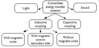
FIG. 1 Classification of contactless/wireless energy transfer systems.
Load position detection and validation on variable-phase contactless
energy transfer desktops
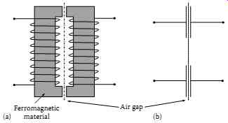 FIG. 2 Inductive (a) and capacitive (b) coupling used in CET systems.
Load position detection and validation on variable-phase contactless energy transfer desktops
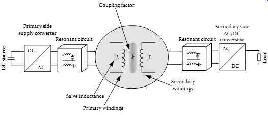
FIG. 3 Block scheme of CET system. Load position detection and validation
on variable-phase contactless energy transfer desktops
2. Basic Principles of Operation
FIG. 3 shows the block diagram of typical inductive coupled CET systems. It consists of primary side DC/AC resonant converter, which converts DC into high-frequency AC energy. Next the AC energy via transformer with inductive coupling factor k is transmitted to the secondary side. The secondary side is not connected electrically with primary and, therefore, can be movable (linearly or/and rotating), giving flexibility, mobility, and safety for supplied loads. In the secondary side, the high-frequency AC energy is converted safely by AC/DC converter to meet the requirements specified by the load parameters.
In most cases, a diode rectifier with capacitive filter is used as AC/DC converter.
However, in some applications an active rectifier or inverter (for stabilized DC or AC loads) is required. Hence, the inductive coupled CET system consists mainly of a large air gap transformer and resonant converter.
2.1 Compensation Topologies
In conventional applications, a transformer is used for galvanic insulation between source and load, and its operation is based on high magnetic coupling factor k between primary and secondary windings. Because of used two-halves cores and/or air gap, CET transformers usually operate under much lower magnetic coupling factor. As a result, the main inductance L12 (see TBL. 1) is very small whereas leakage inductances (L11, L22) are large as compared with conventional transformers.
Consequently, increase in magnetizing current causes higher conducting losses. Also, winding losses increase because of large leakage inductances. Another disadvantage of transformers with relatively large gap is electromagnetic compatibility (EMC) problem (strong radiation). To minimize the above disadvantages of CET transformers, several power conversion topologies have been proposed, which can be classified into the following categories: the flyback, resonant, quasi-resonant, and self-resonant. The common thing for all these topologies is that they all utilize the energy stored in the transformer. In most applications, a resonant soft switching technique is used because it allows both compensation of the transformer leakage inductance and reduction of power converter switching losses. To form resonant circuits and compensate for the large CET transformer leakage inductances, two methods can be applied: S-series or P-parallel, giving four basic topologies: SS,
SP, PS, and PP (first letter denotes primary and second a secondary compensation-see TBL. 1).
The PS and PP topologies require an additional series inductor to regulate the inverter current flowing into the parallel resonant tank. This additional inductor increases EMC distortion, converter size, and the total cost of CET system.
Assuming the same numbers of primary and secondary winding, N1 = N2, the basic parameters of SS and SP topologies have been summarized in TBL. 2, where GV = u2/u1-voltage output-input transfer function of CET system; ω = ωs/ω0-normalized frequency; k-magnetic coupling factor; and
R0-load resistance on the secondary side.
Comparing SS with SP parameters, it can be seen that selected topology influences strongly the correct choice of the primary capacitance. An important advantage of SS topology is that primary capacitance is independent of either magnetic coupling factor or the load. Contrary to this, the SP topology depends on coupling factor and requires higher value of capacitance for stronger magnetic coupling.
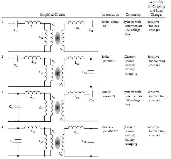
TBL. 1 Variants of Leakage Inductance Compensation Circuits
2.2 Resonant Power Converters
Resonant power converters contain resonant L-C networks, also called resonant circuit (RC) or resonant tank network, whose voltage and current waveforms vary sinusoidally during one or more subintervals of each switching period. These converters contain low total harmonic distortion because switching frequency is equal to first harmonic frequency. Basic power converter topologies used in CET systems are presented in FIG. 4. The full-bridge ( FIG. 4c) inverter, composed of four switches and an RC, is commonly used in high power applications. The half-bridge inverter ( FIG. 4a) has only two switches and two others can be replaced by capacitors ( FIG. 4b). The output voltage μ1 of the fullbridge converter is doubled when compared with half-bridge topology.
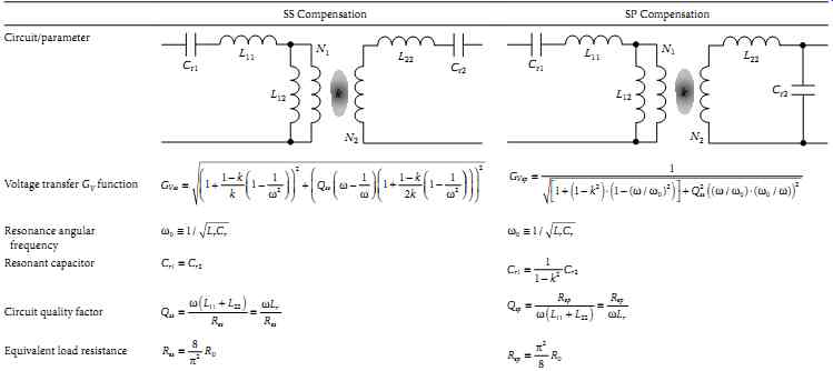
TBL. 2 Basic Parameters of Compensation Circuits

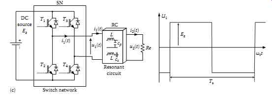
FIG. 4 Basic topologies of series resonant converter and resonant circuit
voltage u1(t) waveforms. (a) Half-bridge unipolar converter, (b) half-bridge
bipolar converter, and (c) full-bridge converter.
The main advantage of resonant technique is reduction of switching losses via mechanisms known as zero current switching (ZCS) and zero voltage switching (ZVS). The switch-on and/or switch-off converter semiconductor components can occur only at zero crossing of the resonant quasi-sinusoidal waveforms. This eliminates some of the switching loss mechanisms. Hence, switching losses are reduced, and resonant converters can operate at switching frequencies that are considerably higher than in comparable pulse width modulation (PWM) hard switching converters. ZVS can also eliminate or reduce some of the electromagnetic emission sources, also known as electromagnetic interference.
Another advantage is that both ZVS and ZCS converters can utilize transformer leakage inductance and diode junction capacitors as well as the output parasitic capacitor of the power switch.
However, resonant converters exhibit several disadvantages. Although, the components of an RC can be chosen such that good performance with high efficiency is obtained at a single operating point, typically it is difficult to optimize the resonant components in such a way that good performance is obtained over a wide range of load currents and input voltages variations. Significant currents may circulate through the tank components, even when the load is removed, leading to poor efficiency at light loads.
Therefore, the converter used in CET system has to be carefully designed.
Typical steady-state waveforms of the voltages u1, u2; currents i1, i2; and primary side power P1 in an insulated gate bipolar transistor-based CET resonant full-bridge converter with series-series compensation for operation at resonance frequency are presented in FIG. 5. The rotatable transformer air gap is 25.5 mm, the load resistance 10 Ω, and transferred power is 2.5 kW. It can be seen that resonant converter operates with zero primary current switching.
3. Review of CET Systems
Depending on the power range and air gap length, different transformer cores can be used. A general overview representing a typical construction of inductive coupling used in CET systems is shown in FIG. 6. It can be seen that for high power and low air gap, transformers with magnetic cores in primary and secondary side are applied. Contrary to this, for large air gap and low power, air transformers (coreless) are preferred. A special case is a sliding transformer that can have construction for linear or circular movement (see Section 35.6). The final configuration of CET systems also depends strongly on the number of loads to be supplied. In such cases, transformers with multi-winding secondary or primary side are used.
In the next subsection, some selected examples of inductive coupled CET systems are presented.
4. CET Systems with Multiple Secondary Winding
The CET system of FIG. 3 can be equipped with multiple secondary winding, as shown in FIG. 7. This is a very flexible solution in which several isolated and/or moving loads can be supplied. In situations when stabilized AC or DC loads are required, an additional active DC/AC or DC/DC converter has to be added ( FIG. 7). Of course, it results in additional losses and efficiency reduction.
Based on this idea, a CET system has been proposed which can be compared to a plug-and socket extension cable. Instead of inserting a plug into a socket, a connection between supply line (cable) and loads (clamps) is established using CET. Also, ABB Corporate Research, Ladenburg, Germany, has developed a factory communication and wireless power supply system for sensors and actuators called WISA. In this solution, a coreless single winding primary side (constructed in form of a frame) is coupled with distributed multiple secondary windings to supply sensors and actuators with 10 mW output power each.
The transformers used in the system of FIG. 7 can have different construction: stationary, rotating, rotatable, with magnetic core, or coreless. As an example a rotating transformer with double parallel connected secondary windings is used in CET systems for the power supply of airborne radar systems.
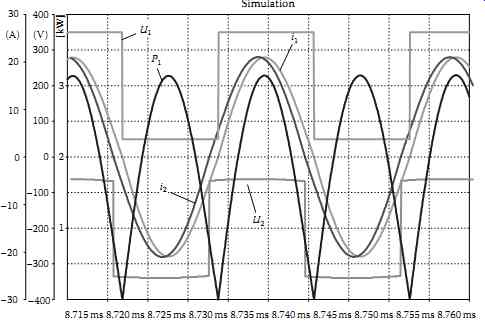
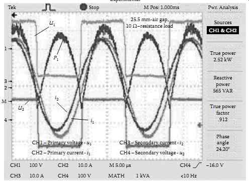
FIG. 5 Steady-state waveforms of the voltages u1, u2; currents i1,
i2; and primary side power P1 in an IGBT transistor-based CET resonant
full-bridge converter with series-series compensation (operation at resonance
frequency).
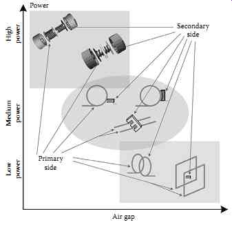
FIG. 6 Power range of inductive coupling-based CET systems versus air
gap wide.
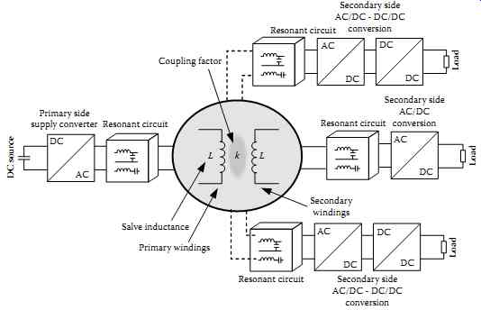
FIG. 7 CET system with multiple secondary winding.
5. CET Systems with Cascaded Transformers
In FIG. 8, a CET system used in power supply for robots and manipulators is shown.
The indirect DC link AC/DC/AC power converter generates a square wave voltage of 200-600 V and 20-60 kHz frequency. This voltage is fed to the primary winding of first rotatable transformer located on the first axis of the robot. The transformer secondary side is connected to the next DC link AC/DC/AC power converter, which using PWM technique generates variable frequency AC voltage to supply first three-phase motor. The transformer secondary side is also connected to the primary side of the next rotatable transformer, which is located on the second joint of the robot. The transformer feeds the second axis drive in similar way as described above for the first machine. More transformers may be added to create arrangement of an AC bus throughout the robot. Similar system is applied for multilayer optical disc used in data storage systems [14]. However, the output power in optical disc is in the range of 20-30 mW, whereas in robots supply is 10-20 kW.
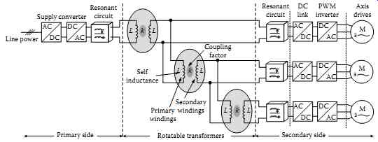
FIG. 8 CET system with cascaded transformers.
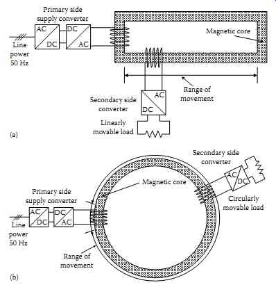
FIG. 9 Basic configuration of CET system with sliding transformer;
(a) for linear movement, (b) for circular movement.
6. CET Systems with Sliding Transformers
The contactless electrical energy delivery systems used in long distance are based on sliding transformers with long primary windings. Basically, two configurations are applied: primary winding forming elongated loop as long as range of receiver movement is required ( FIG. 9a) or circular form for circular movement ( FIG. 9b). The output converter(s) and load(s) are directly connected to secondary winding placed on movable magnetic core.
The sliding magnetic core constructions enable movement of secondary winding along the primary winding loop (Figures 9 and 10). The sliding transformer gives possibility to construct long contactless, electrical energy delivery systems for mobile receivers. These transformer cores are composed of many strips of magnetic materials. Regarding magnetic and mechanical properties, the amorphous or nanocrystalline magnetic materials are preferable. However, when high dynamic properties of mobile receiver are required, some problem may appear because of core inertia. Heavy magnetic core is fixed with the energy receiver ( FIG. 10); therefore, it increases mass of the secondary side. The length of primary winding is in the range of 1-70 m and output power 1-200 kW.
7. CET Systems with Multiple Primary Winding
7.1 Introduction
Electronic devices like mobile phones, multimedia- and music players, laptops, and many more are used daily by countless people all around the world. Many of these devices are fitted with a battery, which allows them to operate independently and without drawing power continuously from the power utility network. However, these devices need to be periodically recharged, since their batteries can only store a finite amount of power. These devices operate with relatively low DC voltage levels (typically 5-12 V) compared to the high utility voltage of 240 V AC (120 V AC in the United States), and thus almost always require an AC-to-DC converter (also called a charger) to accomplish this.
With a multitude of different devices available around the world, it makes for quite a lot of chargers.
Also, most devices come with their own unique chargers. Using various different chargers with unique specifications and plugs can be bothersome and irritating. From a consumer point of view, charging these devices using only one universal charger would be great; it would be even better if this charger could charge multiple devices at a time without even plugging them into a socket, but by simply placing them close to the charger itself.
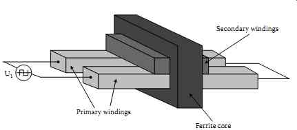
FIG. 10 Example of sliding transformer construction for linearly moving
secondary.
Load position detection and validation on variable-phase contactless energy transfer desktops.
One increasingly popular technology for powering these devices without using adaptors is through the use of CET system. CET is the process in which electrical energy is transferred among two or more electrical devices through inductive coupling as opposed to energy transfer through conventional "plug and socket" connectors.
Different CET charging platforms for these applications have been proposed. One approach is based on a CET charging platform with a single spiral inductor. Here the inductive coupling between the primary inductor and a similar inductor installed into a mobile phone is used to transfer power. With only a single primary and secondary winding however, the phone needs to be placed in a very specific position so that the windings overlap each other exactly. The phone is thus restricted to a certain area wherein it can be charged.
In CET applications where a high degree of freedom regarding the placement of CET devices is required, the use of multiple primary inductors is a popular choice. One such CET charging platform is presented in FIG. 11a. Here multiple planar inductors arranged to form a matrix are embedded in a CET charging platform or into a section of an office table ( FIG. 11b). When small consumer electronic devices, like mobile phones, PDAs, multimedia- and music players, and even laptops fitted with similar inductors are placed on the platform, power is transferred from the CET platform (transmitter) to the CET devices (receivers) through inductive coupling.
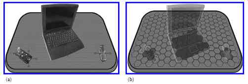
FIG. 11 (a) CET receiver objects randomly placed on a CET-enabled platform
for charging. (b) The CET platform showing multiple inductors underneath
the CET platform.
7.2 Planar Inductor Windings
At the heart of any CET system lies the primary and secondary inductors that form the inductive link and allow power to be transferred between the transmitter and receiver. Their geometries play a vital role in determining the power transfer capability and efficiency of the system. In applications like these, where the size of the inductors, especially the secondary, is very limited, spiral planar winding inductors are often used. Hexagon spiral windings, in particular, use the available surface area very effectively and can be placed in a two-dimensional hexagonal lattice or matrix without any openings between the windings. Furthermore, the distribution of the magnetic field produced by these windings is unique as they produce a strong z-component, which make them especially suited for applications where the primary and secondary inductor placements are parallel to each other. Produced as copper tracks on (flexible) PCB, they can also be easily and cheaply manufactured.
FIG. 12a shows an actual hexagon spiral winding produced on PCB; FIG. 12b shows its graphical representation; and FIG. 12c shows a matrix of hexagon spiral windings.
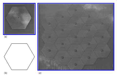
FIG. 12 (a) An actual hexagon spiral winding produced as copper tracks
on a PCB, and (b) its graphical representation used in this work. (c)
A matrix of hexagon spiral windings. Load position detection and validation
on variable-phase contactless energy transfer desktops.
7.3 Electromagnetic Design
The design of a CET system is multidisciplinary in nature and is concentrated in various research fields.
First, and perhaps most importantly, is the electromagnetic investigation. Here, methods for modeling the various important parameters of the CET inductors are created. These include methods for estimating the distribution of the magnetic field intensity, the self- and mutual winding inductances, and their AC resistances. For CET systems void of any soft magnetic materials, as the variable-phase CET desktop presented in, the magnetic vector potential and Biot-Savart methods can be used.
In CET systems where soft magnetic materials are used for shielding purposes, these methods can no longer be directly used. Here, the finite element method is a popular choice.
FIG. 13a and b shows the distribution of the magnetic field as calculated by the developed model.
Here FIG. 13a shows the distribution of the magnetic field in a xy-plane parallel to the winding at a height of 1 mm above the winding, and FIG. 13b shows the magnetic field at 5 mm.
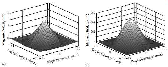
FIG. 13 Distribution of the magnetic field z-component in a xy-plane
parallel to the hexagon spiral inductor calculated at (a) 1 mm above
the inductor, and (b) 5 mm above the inductor.
In general, CET. platforms for these applications use planar inductors with radii between 10 and 30 mm, switching frequencies between 500 kHz and several megahertz. The air gaps are usually limited between 1 and 10 mm.
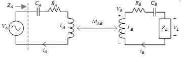
FIG. 14 A simplified schematic diagram of power transfer to load ZL.
7.4 Power Electronics Implementation
The power electronics investigation focuses on the design and implementation of the power electronic systems needed to transfer and control the power delivered over the inductive link. Using the lumped parameters obtained from the electromagnetic investigation, the CET link is modeled as a lossy transformer.
The coupling between the primary and secondary windings is often much weaker compared to traditional iron-cored transformers, and to increase the overall power transfer efficiency, resonance is often used.
The circuit equations that govern the transfer of power from the primary winding to the secondary load can be written in phasor notation: capacitor, acts as a band-pass filter, allowing only the fundamental switching current to flow through in the primary winding.
To control the primary current, and to keep it constant during loaded and non-loaded operations, a PI or hysteresis current controller can also be implemented. This can be programmed in a micro-controller.
Coil commutation circuits are also used in certain CET platforms for switching the current into the different primary windings.
7.5 Operational Features
The CET platform operational features refer to certain technical and non-technical attributes and characteristics that need to be implemented into the system in order to make it user friendly, safe, and operate logically, within its working environment.
One of these important operational features is the location and authentication of valid CET devices placed on the CET platform. From a practical point of view, a CET platform used in an office environment might also contain objects that are not CET-enabled and should not be charged. Some of these objects can be metallic in nature, like a bunch of keys, a soft-drink can, pens, coins, etc. Exciting the primary windings close to these conductive objects could create eddy currents and result in undesired heating of the objects. Other objects, like magnets and ferrites, with high permeability can also interfere with the normal operation of a CET desktop or platform, and should thus be avoided. In a method is devised to locate the position and distinguish between three possible object types placed on the CET platform. These are: metallic objects, magnetic objects, and valid CET devices. FIG. 15a shows a CET platform filled with various CET and non-CET devices. FIG. 15b shows an image of an actual metallic and magnetic materials placed on an implemented CET platform for testing. Here object A is a 60 mm aluminum office key, object B is a toroidal ferrite core, object C is two ferrite E-cores, and object D is a piece of copper plate. Due to their unique influences on the primary winding impedances, they can all be located and distinguished.
Other operational features which could be implemented in a CET platform include periodic scanning of the CET platform to locate newly placed CET devices. Also, audible user feedback tones can be implemented to notify the user when a new CET device is located and powered or when a device is fully charged or removed from the platform. From a safety perspective, the constant monitoring of the current and voltage levels of excited primary windings could indicate potential problems if the values fall outside certain allowed range.
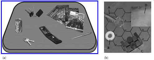
FIG. 15 (a) A CET platform with various CET and non-CET objects randomly
placed on its surface, and (b) image from an actual CET platform showing
a few different metallic and ferrite materials that the CET platform
can distinguish.
[coming soon] TBL. 3 Overview of Inductive Coupled CET Systems
8. Summary and Conclusion
A brief review of basic CET systems, with special focus on inductively coupled solution, is given in this section. Several groups of application with typical specification are summarized in TBL. 3.
Key conclusions include the following:
• The CET systems are used in power range from milliwatts (biomedicine, sensors, actuators, etc.) till several hundred kilowatts (cranes, fast battery charging).
• The final efficiency achieved by inductively coupled CET systems is in the range of 60%-90% for low and high power applications, respectively.
• In high power (>1 kW), transformers with core winding are applied.
• In low power (<100 mW), air gap coupling and very high transmission frequency from 100 kHz till several (MHz) is preferred.
• For long-distance mobile loads, CET systems with sliding transformers are used.
• There is no one standard solution of CET system; every design has to take into account several specific parameters and user conditions.