AMAZON multi-meters discounts AMAZON oscilloscope discounts
Goals:
- • Cite applications of DC motors.
- • Describe the construction and electrical features of DC motors.
- • Draw diagrams of DC motor types.
- • Reverse the direction of rotation of DC motors.
- • Describe base speed, above speed, and below speed.
- • Describe motor connection precautions.
- • Identify DC motor terminal connections.
APPLICATION
The generation of electrical energy and its conversion to mechanical energy is the basis of our industrial structure. It is a fact that DC motors are used primarily for industrial purposes.
By controlling the voltages supplied to the motor windings, a wide range of motor speeds can be obtained. The ability to control the speed of DC motors makes them valuable for factory hoists and cranes, where heavy loads must be started slowly and then accelerated quickly.
DC motors are also used in such precision applications as printing presses and steel mill production operations.
MOTOR CONSTRUCTION
The essential features and parts of DC motors and generators are the same. The DC motor has field coils, armature coils, and a commutator with brushes, ill. 1.
The Field
A strong magnetic field is provided by the field windings of the individual field poles. The magnetic polarity of the field pole system is arranged so that the polarity of any one magnetic field pole is opposite to that of the poles adjacent to it such as north and south. The field structure of a motor has at least two pairs of field poles. However, motors with four or more pairs of field poles are also used.
The Armature
The armature or rotating member of a DC motor is a cylindrical iron assembly mounted directly on the motor shaft, ill. 1.Windings are embedded in slots in the surface of the armature. These windings connect to segments of the commutator. Direct current is fed to the armature windings by carbon brushes, which press against the commutator segments. The commutator changes the direction of the cur rent in the armature conductors as they pass across field poles of opposite magnetic polarity. Continuous rotation in one direction results from these reversals in the armature current.
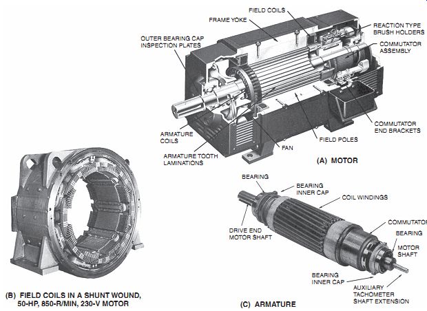
ill. 1 DC motor, field structure, and armature assembly.
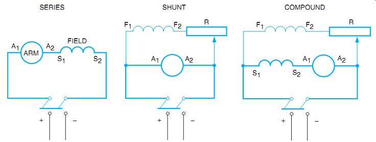
ill. 2 Motor field connections.
Three types of DC industrial motors are widely used: series, shunt, and compound. The type of motor used is based on the mechanical requirements of the applied load.
As shown in ill. 2, the series motor field is connected in series with the armature.
The wire used for the windings must be large enough to pass armature current. The field is labeled S1 and S2.
The field circuit of the shunt motor is connected in shunt (parallel) with the armature.
Rheostat R is connected in the shunt field circuit (F1, F2). The rheostat is used to increase or de crease resistance in the field circuit; this, in turn, varies the magnetic field flux to control the motor speed. The rheostat is external to the motor. The compound motor has both a shunt and a series field winding.
MOTOR ROTATION
The direction of armature rotation of a DC motor depends on the direction of the current in the field and armature circuits. To reverse the direction of rotation, the current direction in either the field or the armature must be reversed.
Reversing the power supply leads does not re verse the direction of armature rotation because, in this case, both the field and the armature currents are reversed.
The direction of rotation of a DC motor is determined by facing the commutator end of the motor, which is generally the rear of the motor.
ill. 3 shows the standard connections for determining the rotation of the series, shunt, and compound motors.
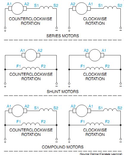
ill. 3 Standard connections to determine rotation of DC motors.
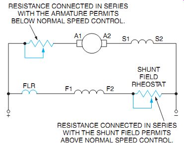
ill. 4 Basic speed control for a DC motor.
One of the major advantages of a DC motor is that it can be operated at different speeds. Nor mal or base speed for a DC motor is obtained by connecting full voltage to both the armature and shunt field. The motor can be operated below normal speed by maintaining rated volt age on the field and reducing the current to the armature. The motor can be operated above normal speed by maintaining rated voltage to the armature and reducing the current flow to the field. Decreasing the field flux causes a de crease in the counter electromotive force (emf) produced in the armature. This permits more armature current to flow and produces a net gain in torque. The motor speed will increase until the motor torque equals the mechanical torque imposed by the load connected to the motor. When a motor will be operated above base speed, the motor manufacturer's specifications should be consulted about the maximum safe operating speed. Don't depend on the controller to protect the motor from excessive speed unless the limit's checked and preset on the controller.
Various methods can be employed to obtain speed control for a DC motor. A method of manual speed control for a compound motor is illustrated in ill. 4. Resistance connected in series with the armature allows the motor to be operated below normal speeds. A shunt field resistor connected in series with the shunt field permits the motor to be operated above normal speeds. A field loss relay (FLR) is connected in series with the shunt field. The FLR is used to disconnect power to the motor should the cur rent flow through the shunt field be lost or drop below a certain level. If the shunt field should open, the motor will become a series motor and could race to a dangerously high speed. A shunt field rheostat is shown in ill. 5.
Most DC speed controllers use solid-state de vices such as SCRs to provide speed control for the motor. As a general rule, the shunt field is provided with constant power and the armature circuit's controlled separately, ill. 6.
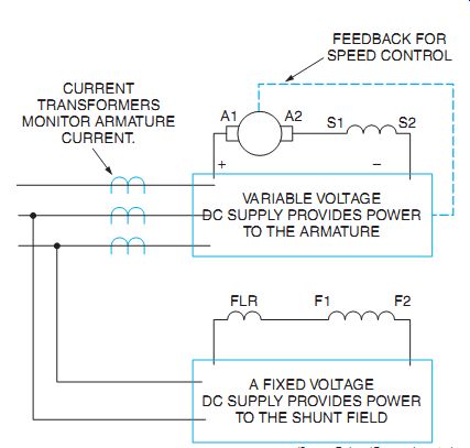
ill. 6 Electronic speed controllers generally provide separate power supplies
for the armature and shunt field.
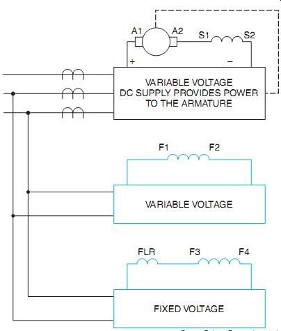
ill. 7 The motor contains two separate shunt field windings.
These controllers generally provide current limit protection and speed regulation. The circuit shown in ill. 6 employs current transformers on the three-phase lines supplying power to the controller to determine motor current. When the current reaches a certain level, the controller simply won't supply more current to the motor. Speed regulation is generally accomplished by a feedback circuit that senses the speed of the motor. If load is added and the motor speed tries to decrease, the controller will supply more armature current. If load is removed and the motor tries to speed up, the controller will decrease armature current.
Notice that in the circuit in ill. 6 the shunt field is connected to a separate power supply. As a general rule the shunt field power remains turned on even when the motor isn't operating. The shunt field acts as a heater to keep moisture from forming in the motor. When servicing or disconnecting a DC motor, make certain that all power to the motor has been disconnected.
There are some controllers that provide over speed control as well as underspeed control.
These controllers use variable voltage to supply current to both the armature and shunt field.
Motors of this type often have two separate shunt fields. One is connected to variable voltage and the other is connected to a constant voltage source, ill. 7. In this way, no matter how weak the shunt field connected to variable volt age becomes, a certain amount of magnetic flux is always produced in the pole pieces.
STARTING THE MOTOR
Two factors limit the current taken by the armature from a DC source: (1) the counter emf and (2) the armature resistance. Because there is no counter emf when the armature is at a standstill and its resistance is very low, the current taken by the armature will be abnormally high. As a result, the armature current must be limited by an external resistor or a starting rheostat. This procedure is described in the following units. With solid-state equipment, the current flow is limited by allowing a gradual increase of current strength to start the motor.
QUIZ
1. Draw diagrams of the following DC motors, including the proper terminal markings and field rheostats.
a. series
b. shunt
c. compound
2. How is the direction of rotation of a DC motor reversed?
3. Why is the shunt field circuit never allowed to open while operating?
4. What is the function of the field loss relay?
5. Why is it common practice to leave power connected to the shunt field even when the motor isn't operating?
6. Explain why reducing current flow to the shunt field causes the motor speed to increase.