AMAZON multi-meters discounts AMAZON oscilloscope discounts
Goals:
- • Describe how an out-of-step relay protects the starting winding of a synchronous motor.
- • Describe the action of a polarized field frequency relay in applying and removing DC field excitation on a synchronous motor.
- • Connect synchronous motors and controllers that use out-of-step relays and polarized field frequency relays to achieve automatic motor synchronization.
- • Recommend troubleshooting solutions for problems.
An automatic synchronous motor starter can be used with a synchronous motor to provide automatic control of the startup sequence. That is, the controller automatically sequences the operation of the motor so that the rotor field is synchronized with the revolving magnetic field of the stator.
There are two basic methods of starting synchronous motors automatically. In the first method, full voltage is applied to the stator winding. In the second method, the starting voltage is reduced. A commonly used method of starting synchronous motors is the across-the line connection. In this method, the stator of the synchronous motor is connected directly to the plant distribution system at full voltage. A magnetic starter is used in this method of starting.
A polarized field frequency relay can be used for the automatic application of field excitation to a synchronous motor.
ROTOR CONTROL EQUIPMENT
Field Contactor
The field contactor opens both lines to the source of excitation, ill. 1. During starting, the contactor also provides a closed field circuit through a discharge resistor. A solenoid operated field contactor is similar in appearance to the standard DC contactor. However, for this DC operated contactor, the center pole is normally closed. It is designed to provide a positive overlap between the normally closed contact and the two normally open contacts. This over lap is an important feature because it means that the field winding is never open. The field winding of the motor must always be short-circuited through a discharge resistor or connected to the DC line. The coil of the field contactor is operated from the same direct-current source that provides excitation for the synchronous motor field.
Out-of-Step Relay
The squirrel cage winding, or starting (amortisseur) winding, won't overheat if a synchro nous motor starts, accelerates, and reaches synchronous speed within a time interval deter mined to be normal for the motor. In addition, the motor must continue to operate at synchro nous speed. Under these conditions, adequate protection for the entire motor is provided by three overload relays in the stator winding. The squirrel cage winding, however, is designed for starting only. If the motor operates at sub-synchronous speed, the squirrel cage winding may overheat and be damaged. It isn't unusual for some synchronous motors to withstand a maximum locked rotor interval of only 5 to 7 seconds.
An out-of-step relay (OSR), ill. 2, is provided on automatic synchronous starters to protect the starting winding. The normally closed contacts of the relay will open to de-energize the line contactor under the following conditions:
1. The motor does not accelerate and reach the synchronizing point after a preset time delay.
2. The motor does not return to a synchronized state after leaving it.
3. The amount of current induced in the field winding exceeds a value determined by the core setting of the out-of-step relay.
As a result, power is removed from the stator circuit before the motor overheats.
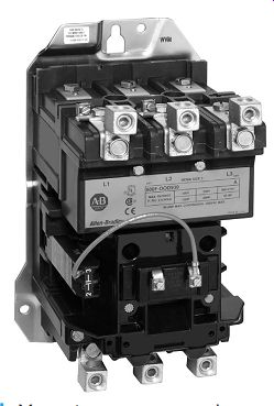
ill. 1 Magnetic contactor used on synchronous starter for field control.
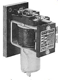
ill. 2 Out-of-step relay used on synchronous starters.
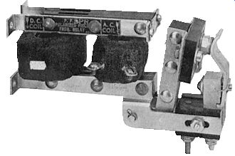
ill. 3 Polarized field frequency relay with contacts in normally closed position.
Polarized Field Frequency Relay
A synchronous motor is started by accelerating the motor to as high a speed as possible from the squirrel cage winding and then applying the DC field excitation. The components responsible for correctly and dependably applying and removing the field excitation are a polarized field frequency relay (PFR) and a reactor, ill. 3.
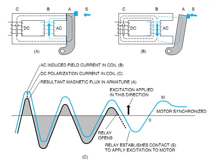
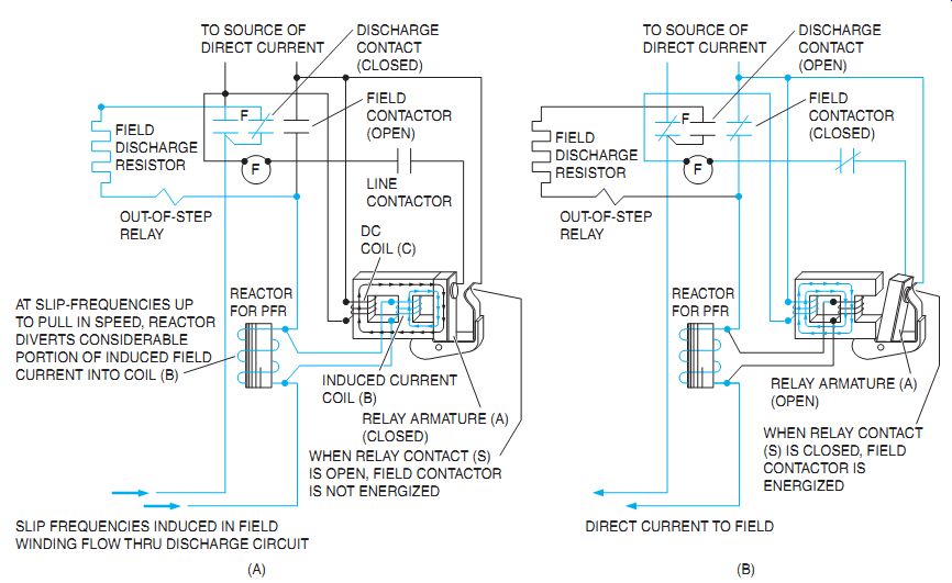
ill. 4 Polarized field frequency relay operation.
The operation of the frequency relay is shown in ill. 4. The magnetic core of the relay has a direct-current coil (C), an induced field current coil (B), and a pivoted armature (A) to which contact (S) is attached. Coil C is connected to the source of DC excitation. This coil establishes a constant magnetic flux in the relay core. This flux causes the relay to be polarized. Superimposed on the magnetic flux in the relay core is the alternating magnetic flux produced by the alternating induced rotor field current flowing in coil B. The flux through armature A depends on the flux produced by AC coil B and DC coil C. Coil B produces an alternating flux of equal positive and negative magnitude each half-cycle. Thus, the combined flux flowing through armature (A) is much larger when the flux from coil B opposes that from coil C.
In ill. 4(A), the flux from coil B opposes the flux from DC coil C, resulting in a strong flux being forced through armature A of the relay. This condition is shown by the lower shaded loops of ill. 4(C). One-half cycle later, the flux produced by coil B reverses and less flux flows through armature A. This is due to the fact that the flux from coil B no longer forces as much flux from coil C to take the longer path through armature A. The resultant flux is weak and is illustrated by the small, upper shaded loops of ill. 4(C).The relay armature opens only during the period of the induced field current wave, which is represented by the small, upper loops of the relay armature flux.
As the motor reaches synchronous speed, the induced rotor field current in relay coil B de creases in amplitude. A value of relay armature flux (upper shaded loop) is reached at which the relay armature A no longer stays closed.
The relay then opens to establish contact S. DC excitation is then applied at the point indicated on the induced field current wave.
Excitation is applied in the direction shown by the arrow. The excitation is opposite in polarity to that of the induced field current at the point of application. This requirement is necessary to compensate for the time needed to build up excitation. The time interval results from the magnetic inertia of the motor field winding.
Because of the inertia, the DC excitation does not become effective until the induced current reverses (point O on the wave) to the same polarity as the direct current. The excitation continues to build up until the motor is synchronized as shown by point M on the curve.
ill. 5 indicates the normal operation of the frequency relay. DC excitation is applied to the coil of the relay at the instant the synchro nous motor is started. When the stator winding is energized, using either full-voltage or reduced voltage methods, line current is allowed to flow through the three overload relays and the stator winding. Line frequency currents are induced in the two electrically independent circuits of the rotor: (1) the squirrel cage or starting windings and (2) the field windings. The current induced in the field windings flows through the reactor.
This device shunts part of the current through the AC coil of the frequency relay, the coil of the out-of-step relay, the field discharge resistor, and finally to the normally closed contact of the field contactor. The flux established in the frequency relay core pulls the armature against the spacer and opens the normally closed relay contacts, ill. 5. As the motor accelerates to the synchronous speed, the frequency of the induced currents in the field windings diminishes. There is, however, sufficient magnetic flux in the relay core to hold the armature against the core. This flux is due to a considerable amount of induced current forced through the AC coil of the frequency relay by the impedance of the reactor at high slip frequency.
At the point where the motor reaches its synchronizing speed (usually 92 to 97 percent of the synchronous speed) the frequency of the induced field current is at a very low value. The reactor impedance is also greatly reduced at this low frequency. Thus, the amount of current shunted to the AC coil is reduced to the point where the resultant core flux is no longer strong enough to hold the armature against the spacer.
At the moment that the rotor speed and the frequency and polarity of the induced currents are most favorable for synchronization, the armature is released, the relay contacts close, and the control circuit's completed to the operating coil of the field contactor. DC excitation is applied to the motor field winding, ill. 5(B).
At the same time, the out-of-step relay and discharge resistor are de-energized by the normally closed contacts of the field contactor.
An overload or voltage fluctuation may cause the motor to pull out of synchronism. In this case, a current at the slip frequency is induced in the field windings. Part of this current flows through the AC coil of the polarized field frequency relay, opens the relay contact, and re moves the DC field excitation. The motor automatically resynchronizes if the line voltage and load conditions return to normal within a pre set time interval, and the motor has enough pull-in torque. However, if the overload and low-voltage conditions continue so that the motor cannot resynchronize, then either the out-of-step relay or the overload relays activate to protect the motor from overheating.
ill. 5 Wiring connections and operation of a polarized field frequency relay.
SUMMARY OF AUTOMATIC STARTER OPERATION
The line diagram in ill. 6 shows the automatic operation of a synchronous motor. For starting, the motor field winding is connected through the normally closed power contact of the field contactor (F), the discharge resistor, the coil of the out-of-step relay, and the reactor.
When the start button is pressed, the circuit's completed to the control relay coil (CR1) through the control fuses, the stop button, and contacts of the overload and out-of-step relays.
The closing of CR1 energizes the line contactor M, which applies full voltage at the motor terminals with overload relays in the circuit. A normally open contact on CR1 and a normally open interlock on line contactor M provide the hold in, or maintaining, circuit. The starting and running current drawn by the motor is indicated by an ammeter with a current transformer.
At the moment the motor starts, the polarized field frequency relay (PFR) opens its normally closed contact and maintains an open circuit to the field contactor (F) until the motor accelerates to the proper speed for synchronizing.
When the motor reaches a speed equal to 92 to 97 percent of its synchronous speed, and the rotor is in the correct position, the contact of the polarized field frequency relay closes to energize field contactor F through an interlock on line contactor M. The closing of field contactor F applies the DC excitation to the field winding and causes the motor to synchronize. After the rotor field circuit's established through the normally open power contacts of the field contactor, the normally closed contact on this contactor opens the discharge circuit. The motor is now operating at the synchronous speed. If the stop button is pressed, or if either magnetic overload relay is tripped, the starter is de-energized and disconnects the motor from the line.
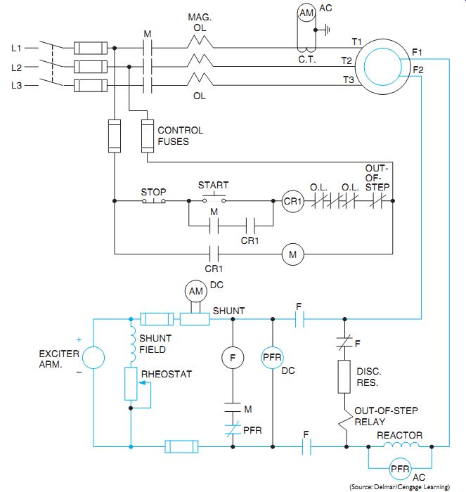
ill. 6 Line diagram for automatic operation of synchronous motor using polarized
field frequency relay.
BRUSHLESS SOLID-STATE MOTOR EXCITATION
An improvement in synchronous motor excitation is the development of the brushless DC exciter. The commutator of a conventional direct-connected exciter is replaced with a three phase, bridge-type, solid-state rectifier. The DC output is then fed directly to the field winding.
A simplified circuit's shown in ill. 7.
This scheme is similar to that of a brushless generator. The motor mounted exciter receives its excitation and control (normally supplied with the line control unit) from a small rectifier and adjustable autotransformer supplied from the AC power source. Alternating current from the exciter is fed to a rectifier diode assembly.
The DC output of the rectifier is controlled by the static field application system. A rotor mounted, field-discharge resistor provides a discharge path for the motor induced field cur rent during starting. The frequency-sensitive static field application system replaces the polarized field frequency relay, the reactor, and the field contactor of conventional brush-type motors. It applies field excitation in such a way that maximum pull-in torque is obtained when the motor reaches a synchronizing speed. Field excitation is automatically removed if the motor is out of step. A field monitoring relay (normally supplied with a line control unit) pro vides instantaneous shutdown or unloading on pull-out and provides out-of-step protection for the squirrel cage winding of the motor.
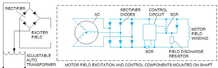
ill. 7 Elementary diagram of a brushless solid-state motor field excitation.
QUIZ:
1. What are the two basic methods of automatically starting a synchronous motor?
2. What is an out-of-step relay?
3. Why is an out-of-step relay used on automatic synchronous starters?
4. Under what conditions will the out-of-step relay trip out the control circuit?
5. What is the last control contact that closes on a starting and synchronizing operation?
6. What influence do both of the polarized field frequency relay (PFR) coils exert on the normally closed contact?
7. Why is the PFR polarized with a DC coil?
8. Approximately how much time (in terms of electrical cycles) elapses from the moment the PFR opens to the moment the motor actually synchronizes?
9. How does the AC coil of the PFR receive the induced field current without receiving the full field current strength?
10. Why is a control relay (CR1) used in ill. 6?
11. On a brushless rotor, how is DC obtained?