AMAZON multi-meters discounts AMAZON oscilloscope discounts
Goals:
• Describe the purpose of starting motors in sequence.
• Read and interpret sequence control diagrams.
• Make the proper connections to operate motors in sequence.
• Troubleshoot sequence motor control circuits.
• Describe solid-state logic elements.
• Describe solid-state logic concept and control function.
Sequence control is the method by which starters are connected so that one cannot be started until the other is energized. This type of control is required whenever the auxiliary equipment associated with a machine, such as high-pressure lubricating and hydraulic pumps, must be operating before the machine itself can be operated safely. Another application of sequence control is in main or subassembly line conveyors.
The proper push-button station connections for sequence control are shown in ill. 1.
Note that the control circuit of the second starter is wired through the maintaining contacts of the first starter. As a result, the second starter is prevented from starting until after the first starter is energized. If standard starters are used, the connection wire (X) must be removed from one of the starters.
If sequence control is to be provided for a series of motors, the control circuits of the additional starters can be connected in the manner shown in ill. 2. That is, M3 will be connected to M2 in the same step arrangement by which M2 is connected to M1.
The stop button or an overload on any motor will stop all motors with this method.
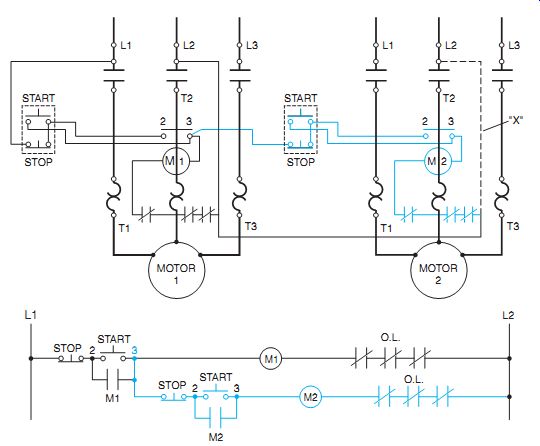
ill. 1 Standard starters wired for sequence control. (Rockwell Automation)
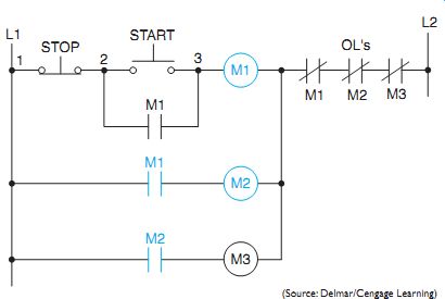
ill. 2 Auxiliary contacts (or interlocks) used for automatic sequence control.
Contact (M1) energizes coil (M2); contact (M2) energizes coil (M3).
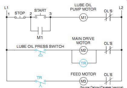
ill. 3 Pilot devices used in an automatic sequence control scheme.
AUTOMATIC SEQUENCE CONTROL
A series of motors can be started automatically with only one start-stop control station as shown in ill. 2 and ill. 3. When the lube oil pump, (M1) in ill. 3, is started by pressing the start button, the pres sure must be built up enough to close the pressure switch before the main drive motor (M2) will start. The pressure switch also energizes a timing relay (TR). After a preset time delay, the contact (TR) will close and energize the feed motor starter coil (M3).
If the main drive motor (M2) becomes over loaded, the starter and timing relay (TR) will open. As a result, the feed motor circuit (M3) will be de-energized due to the opening of the contact (TR). If the lube oil pump motor (M1) becomes overloaded, all of the motors will stop. Practically any desired overload control arrangement is possible. ill. 4 reviews some common overload control arrangements for operating different machinery control schemes.
Different Voltages
ill. 5 illustrates sequencing control connections using different operating voltages.
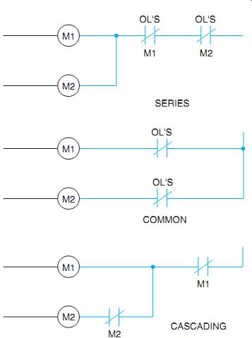
ill. 4 Common overload connections.
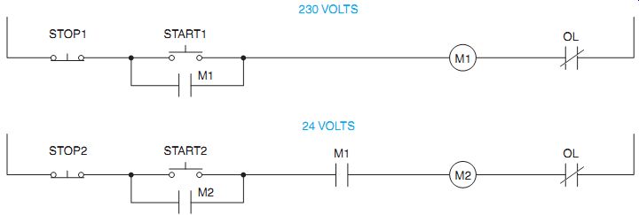
ill. 5 Different voltage sequencing.
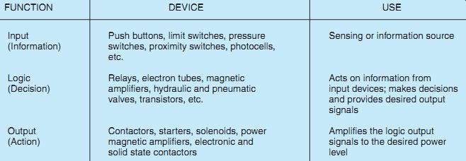
Table 1 -- Functions and Their Associated Devices
FUNCTION: Input (Information) Logic (Decision) Output (Action)
DEVICE: Push buttons, limit switches, pressure switches, proximity switches, photocells, etc.
Relays, electron tubes, magnetic amplifiers, hydraulic and pneumatic valves, transistors, etc.
Contactors, starters, solenoids, power magnetic amplifiers, electronic and solid state contactors
USE: Sensing or information source Acts on information from input devices; makes decisions and provides desired output signals Amplifies the logic output signals to the desired power level
LOGIC CONCEPT AND CONTROL FUNCTION
The functions of electrical control systems and their associated devices can be grouped into three functions: input, logic, output. Table 1 shows the function, devices, and their use.
The input, or information, section of control consists of limit switches, pressure switches, push buttons, temperature sensors, and other control devices. These accessories receive and transmit information to the logic, or decision, section of the control, such as a relay or transistor. When information has been received, it must be assimilated and correlated in order to arrive at a decision to act or do something, the output.
Once a decision has been reached, the control must take action or have an output. Typical actions include energizing a solenoid, contactor or motor starter, an indicating light, or other electrical apparatus where something takes place.
Solid-state control performs the same decision-making function in a solid-state system that relays perform in a conventional magnetic system. Relays convert a single input from a push button to a coil into multiple outputs by means of a movable armature closing and opening contacts. Solid-state control logic elements convert a single input, or combination of inputs, into a single output by controlling a transistor.
The development of solid-state control has introduced new concepts and terminology to the electrical industry. This is true even though solid-state control functionally duplicates conventional magnetic control devices. It is in the area of performing the logic function that solid state control is applied.
SOLID-STATE LOGIC ELEMENTS
Motor control circuits sometimes involve a special type of electronic logic called "gate logic." Gate logic generally involves the use of integrated circuits. There are five basic types of gates: AND, OR, INVERTER, NOR, and NAND.
Gate logic differs from relay logic in several ways. Logic gates are solid-state devices, and as such they operate much faster, are not subject to vibration, and have no moving components.
Another difference between gate logic and relay logic is that relays are single input (the coil), multi-output (the contacts) devices. Logic gates are multi-input, single output devices; they contain two or more inputs but only one output.
There are also different sets of symbols used to depict logic gates. One set is the USASI standard, generally referred to as computer logic, and the other set is the NEMA standard.
The AND Gate
The AND gate requires all of its inputs to be in a high state or turned on (voltage applied to the input) before it will develop a high output.
The USASI and NEMA symbols for a two-input AND gate are shown in ill. 6. The inputs are labeled A and B and the output is labeled Y.
The AND gate equivalent logic is two normally open switches connected in series. In order to provide an output to the lamp, both switches must be changed from open to closed.
The OR Gate
The OR gate will have a high output if any or all of its inputs are high. The OR gate equivalent logic would be normally open switches connected in parallel. If either or both of the switches should change from open to closed, the lamp would turn on. The USASI and NEMA symbols for an OR gate are shown in ill. 7.
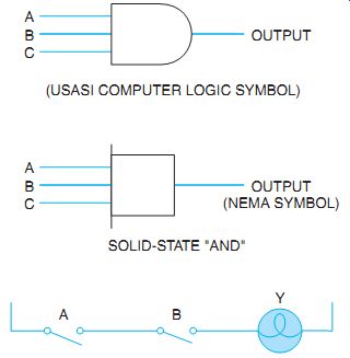
ill. 6 An AND gate must have all inputs high before it can have an output.
(USASI COMPUTER LOGIC SYMBOL); SOLID-STATE "AND" OR GATE SYMBOL;
NEMA LOGIC OR GATE SYMBOL
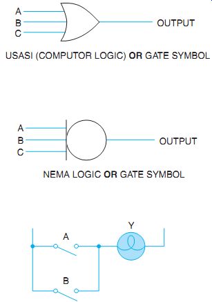
ill. 7 An OR gate will have a high output if any or all of its inputs are
high.
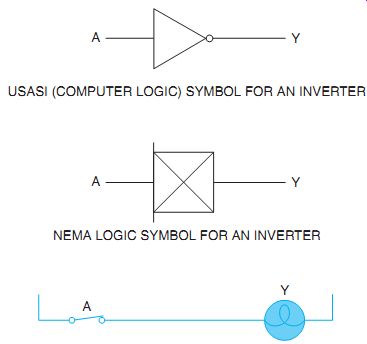
ill. 8 The output of an INVERTER will always be the opposite of the input.
USASI (COMPUTER LOGIC) SYMBOL FOR AN INVERTER; NEMA LOGIC SYMBOL FOR AN INVERTER
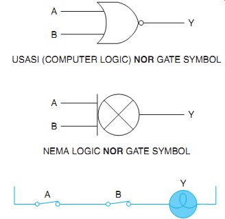
ill. 9 A NOR gate will have a low input if any input is high.
USASI (COMPUTER LOGIC) NOR GATE SYMBOL; NEMA LOGIC NOR GATE SYMBOL
The INVERTER
The INVERTER is a single-input, single output device. The output will always be inverted or opposite the input. If the input is high, the output will be low; if the input is low, the output will be high. In the USASI standard symbols, a circle is used to represent an inverted condition. The NEMA standard symbols use an "X" to represent an inverted input or output. The logic of an INVERTER is a normally closed contact connected in series with the output. As long as the contact is de-energized (not opened) the output will be high. When the input is energized (contact changed) the output will be low. The USASI and NEMA symbols for an INVERTER are shown in ill. 8.
The NOR Gate
A NOR gate is actually an abbreviation for "NOT OR GATE." The NOR gate is an OR gate with an inverted output. The logic of an OR gate is any high input will produce a high output.
Conversely, the logic of the NOR gate is that any high input will produce a low output. An equivalent switch circuit for the NOR gate would be normally closed switches connected in series. If any switch should be energized or changed, there will be a low output. The USASI and NEMA logic symbols for a NOR gate are shown in ill. 9.
The NAND Gate
NAND is an abbreviation for "NOT AND." The NAND gate is the same as an AND gate with an INVERTER connected to the output.
The logic of an AND gate is that if any input is low, the output also will be low. The logic of a NAND gate is that if any input is low, the output will be high. The equivalent switch circuit for a NAND gate would be normally closed switches connected in parallel. The USASI and NEMA symbols for a NAND gate are shown in ill. 10.
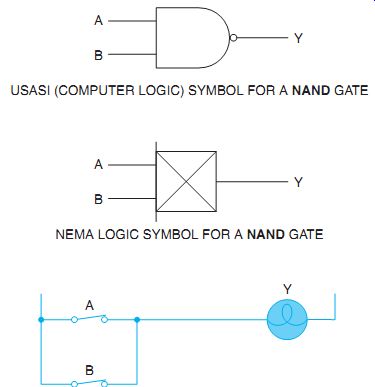
ill. 10 Any low input will produce a high output for a NAND gate. USASI (COMPUTER
LOGIC) SYMBOL FOR A NAND GATE; NEMA LOGIC SYMBOL FOR A NAND GATE
The EXCLUSIVE OR Gate
Another type of gate that's derived from an OR gate is called the EXCLUSIVE OR gate. The logic of a two-input EXCLUSIVE OR gate is that if either but not both of its inputs is high it will have a high output. If both inputs are low, the output will be low. If both inputs are high, the output will also be low. The USASI symbol and equivalent switch circuit for an EXCLU SIVE OR gate are shown in ill. 11.
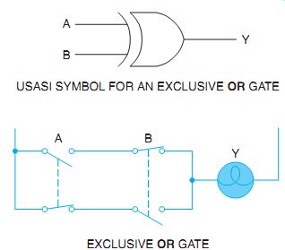
ill. 11 Exclusive OR gate. USASI SYMBOL FOR AN EXCLUSIVE OR GATE; EXCLUSIVE
OR GATE
QUIZ:
1. Describe what is meant by sequence control.
2. Referring to the diagram in ill. 2, explain what will happen if the motor that's operated by coil "M" becomes overheated.
3. In ill. 2, what will happen if there is an overload on motor 2?
4. What is the sequence of operation in ill. 2?
5. Redraw ill. 3 so that if the feed motor (M3) is tripped out because of overload, it will also stop the main drive motor (M2).
6. Draw a symbol for a solid-state logic element "AND."