AMAZON multi-meters discounts AMAZON oscilloscope discounts
Goals:
• Explain the purpose of the various interlocking methods.
• Read and interpret wiring and line diagrams of reversing controls.
• Read and interpret wiring and line diagrams of interlocking controls.
• Wire and troubleshoot reversing and interlocking controls.
The direction of rotation of three-phase motors can be reversed by interchanging any two motor leads to the line. If magnetic control devices are to be used, then reversing starters accomplish the reversal of the motor direction, ill. 1. Reversing starters wired to NEMA standards interchange lines L1 and L3, ill. 2. To do this, two contactors for the starter assembly are required-one for the forward direction and one for the reverse direction, ill. 3. A technique called interlocking is used to prevent the contactors from being energized simultaneously or closing together and causing a short circuit. There are three basic methods of interlocking.
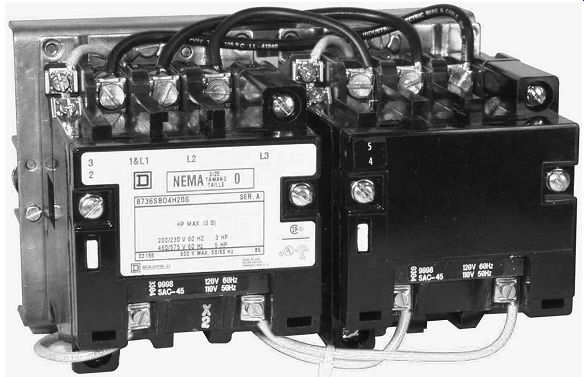
ill. 1 Horizontal reversing starter shown without overload relay. (e.g., made
by Schneider Electric)
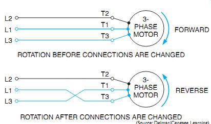
ill. 2 Reversing rotation of an induction motor.
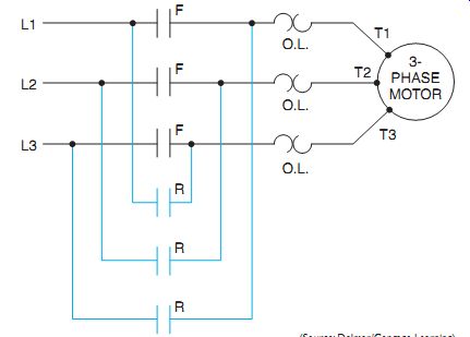
ill. 3 Elementary diagram of a reversing starter power circuit.
MECHANICAL INTERLOCK
A mechanical interlocking device is assembled at the factory between the forward and reverse contactors. This interlock locks out one contactor at the beginning of the stroke of either contactor to prevent short circuits and burnouts.
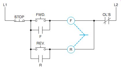
The mechanical interlock between the contactors is represented in the elementary diagram of ill. 4 by the broken line between the coils. The broken line indicates the coils F and R cannot close contacts simultaneously because of the mechanical interlocking action of the device.
When the forward contactor coil (F) is energized and closed through the forward push but ton, the mechanical interlock prevents the accidental closing of coil R. Starter F is blocked by coil R in the same manner. The first coil to close moves a lever to a position that prevents the other coil from closing its contacts when it's energized. If an oversight allows the second coil to remain energized without closing its contacts, the excess current in the coil due to the lack of the proper inductive reactance will dam age the coil.
Note in the elementary diagram of ill. 4 that the stop button must be pushed before the motor can be reversed.
Reversing starters are available in horizontal and vertical construction. A vertical starter is shown in ill. 5.
A mechanical interlock is installed on the majority of reversing starters in addition to the use of one or both of the following electrical methods: push-button interlock and auxiliary contact interlock.
ill.
4 Mechanical interlock between the coils pre vents the starter from closing
all contacts simultaneously. Only one contactor can close at a time.
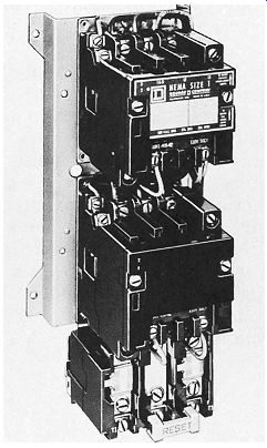
ill. 5 Vertical reversing motor starter. (Schneider Electric)
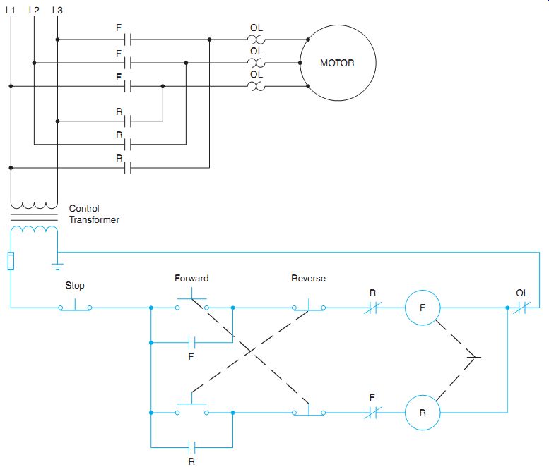
ill. 6 Elementary diagram of the reversing starter shown in ill. 1.The mechanical,
push-button, and auxiliary contact interlock are indicated.
PUSH-BUTTON INTERLOCK
Push-button interlocking is an electrical method of preventing both starter coils from being energized simultaneously.
When the forward button in ill. 6 is pressed, coil F is energized and the normally open (NO) contact F closes to hold in the forward contactor. Because the normally closed (NC) contacts are used in the forward and reverse push-button units, there is no need to press the stop button before changing the direction of rotation. If the reverse button is pressed while the motor is running in the forward direction, the forward control circuit's de-energized and the reverse contactor is energized and held closed.
Repeated reversals of the direction of motor rotation are not recommended. Such reversals may cause the overload relays and starting fuses to overheat; this disconnects the motor from the circuit. The driven machine may also be damaged. It may be necessary to wait until the motor has coasted to a standstill.
NEMA specifications call for a starter to be de-rated. That is, the next size larger starter must be selected when it's to be used for "plugging" to stop, or "reversing" at a rate of more than five times per minute.
Reversing starters consisting of mechanical and electrical interlocked devices are preferred for maximum safety.
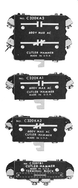
ill. 7 Electrical interlocks and terminal blocks. AUXILIARY CONTACT INTERLOCK
(e.g., as made by Eaton Corporation)
Another method of electrical interlock consists of normally closed auxiliary contacts on the forward and reverse contactors of a reversing starter, ill. 6.
When the motor is running forward, a normally closed contact (F) on the forward contactor opens and prevents the reverse contactor from being energized by mistake and by closing.
The same operation occurs if the motor is running in reverse. Electrical interlocks are usually mounted on the side of a motor starter.
These are shown in ill. 7.
The term interlocking is also used generally when referring to motor controllers and control stations that are interconnected to provide control of production operations.
To reverse the direction of rotation of single phase motors, either the starting or running winding motor leads are interchanged, but not both. A schematic diagram showing the connection for reversing the direction of rotation for a single-phase motor is shown in ill. 8. A wiring diagram of this connection is shown in ill. 9.
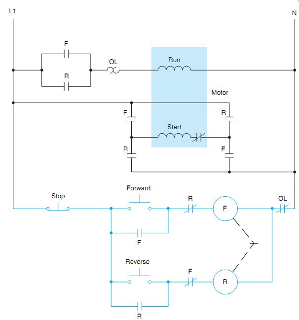
ill. 8 Reversing the direction of rotation of a single-phase motor.
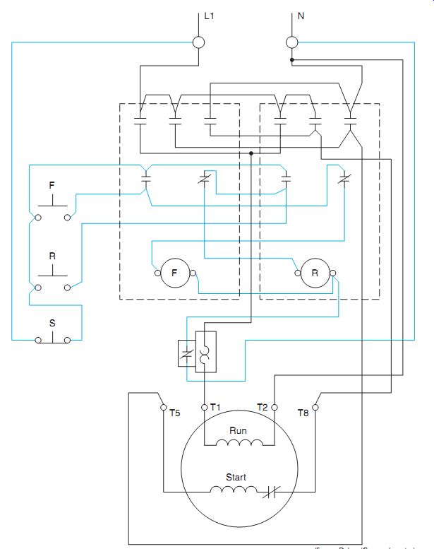
ill. 9 Wiring diagram of single-phase motor reversing control.
QUIZ:
1. How is a change in the direction of rotation of a three-phase motor accomplished?
2. What is the purpose of interlocking?
3. If a reversing control circuit contains push-button interlocking, what would happen if both the forward and reverse buttons were pushed at the same time?
4. How is auxiliary contact interlocking achieved on a reversing starter?
5. After the forward coil has been energized, is the auxiliary forward interlocking con tact open or closed?
6. If a mechanical interlock is the only means of interlocking used, what procedure must be followed to reverse the direction of the motor? Assume the motor to be running forward.
7. If pilot lights are to indicate which coil is energized, where should they be connected? Additional auxiliary contacts are not to be used.
8. What is the sequence of the operations if the limit switches, shown in ill. 6, are used. (Limit switches were covered in Unit 13.)
9. What will happen in ill. 6 if limit switches are installed and the jumpers from terminals 6 and 7 to the coils are not removed?
10. In place of the push buttons in ill. 4, draw a heavy-duty selector switch for forward-reverse-stop control. Show the target table for this selector switch.
11. From the elementary drawing in ill. 10, determine the number and terminal identification of the wiring in each conduit in the conduit layout. Indicate your solutions in the same manner as the example given below the disconnect switch.
12. Convert the control circuit only, ill. 11, from the wiring diagram to an elementary diagram. Include the limit switches (RLS, FLS) as operating in the control circuit.
13. Draw a standard duty selector switch to select either forward or reverse. Include a stop and run push button. Include proper interlocks.