AMAZON multi-meters discounts AMAZON oscilloscope discounts
Goals
• Draw an elementary line diagram using a wiring diagram as a reference.
• Describe the different advantages of two- and three-wire controls.
• Connect motor starters with two- and three-wire controls.
• Identify common terminal markings.
• Read and use target tables.
• Connect drum reversing controllers.
• Interpret motor nameplate information.
• Connect dual-voltage motors.
LINE DIAGRAMS AND WIRING DIAGRAMS
Most electrical circuits can be represented by two types of diagrams: a wiring diagram and a line diagram. Wiring diagrams include all of the devices in the system and show the physical relationships between the devices. All poles, terminals, contacts, and coils are shown on each device. These diagrams are particularly useful in wiring circuits because the connections can be made exactly as they appear on the diagram, a wire for every line. A wiring diagram gives the necessary information for the actual wiring of a circuit and provides a means of physically tracing the wires for troubleshooting purposes or when normal preventative maintenance is necessary. In other words, the actual physical installation and the wiring diagram coincide as far as the locations of the devices and wiring are concerned.
The wiring diagram is quite often such a maze of lines that it may be nearly impossible to deter mine the electrical sequence of operation of the circuits shown. For this reason, a rearrangement of the circuit elements is made to form what is called a line diagram. Line diagrams, also called elementary, schematic, and ladder diagrams, are widely used in industry. It is a decided advantage to an electrician to learn to use these diagrams.
The line diagram also represents the electrical circuit but does so in the simplest manner possible. No attempt is made to show the various devices in their actual physical positions.
All control devices are shown located between vertical lines that represent the source of control power. Circuits are shown connected as directly as possible from one of the source lines horizontally--through contacts and current consuming devices--to the other source line. All connections are made so that the functions and sequence of operations of the various devices and circuits can be traced easily. The schematic diagram is invaluable in troubleshooting because it shows the effect that opening or closing various contacts have on other devices in the circuit. The schematic diagram attempts to convey as much information as possible with the least amount of confusion. It shows you in the simplest manner how an electrical control system should work.
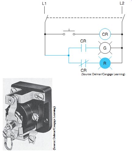
Fig. 1 A single-pole, double-throw (SPDT) control relay and its schematic
diagram.
Any single operation of a piece of electrical equipment is usually not complicated. However, when a sequence of operations to be completed by electrical means depends on the present, previous, or subsequent operations of several other pieces of equipment, the number of operations forms a complex system that may be difficult to understand. The line diagram reduces the necessary information to the simplest possible form to help the electrician understand the operation of the total control system.
FIG. 1 illustrates the simplicity of an elementary or schematic diagram. Note how easy it is to trace through the circuit: When the disconnect switch is closed, current flows through the only complete path-L1 down through the normally closed contact CR, through the red pilot lamp to L2.When the normally open push button is closed, CR coil is energized through the complete circuit to L2 from L1. When the control relay is energized, it instantly closes the normally open CR contact to energize the green indicating lamp. At the same time, it opens normally closed contact CR, interrupting the circuit to the red lamp. When the push button is released, the red lamp is again lit and the green lamp goes out because the coil is now de energized. The normally open CR contact opens and normally closed CR contact closes.
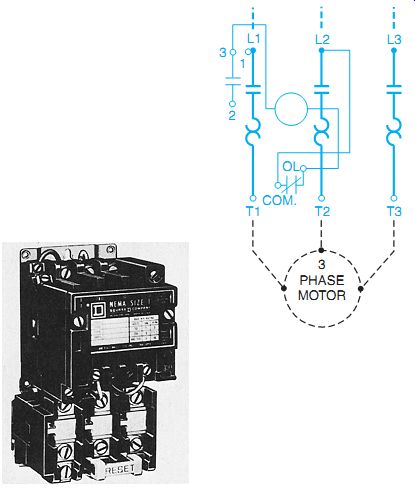
Fig. 2 AC magnetic motor starter
Study FIG. 2 to become familiar with a motor starter as it is represented by a wiring diagram. The principal parts of the starter are labeled on the diagram so that a comparison can be made with the actual starter. This study should help you to visualize the starter when viewing a wiring diagram and will help in making correct connections when the starter is actually wired. Note that the wiring diagram shows as many parts as possible in their proper relative positions. It is not necessary to show the armature and crossbar or the overload reset mechanism of the starter in the wiring diagram because these parts are not involved in the actual wiring. The control circuit consists of the coil, the contacts of the overload relays, and the coil-holding contact for the control circuit. The power circuit consists of the main contacts and the overload heaters to the motor. Note the heavier lines used for the power circuit. The broken lines show where the power lines and motor leads connect to the starter.
The wiring diagram in FIG. 2 represents a size 1 motor starter. Other starter sizes have similar diagrams and are wired in a similar manner. Some of the connections, however, may not have the same physical locations on the starters.
It should be noted that the control circuit in FIG. 2 shows the motor starter coil connected directly across the incoming power line. This type of circuit is known as a line voltage control circuit. The coil of the motor starter must have the same voltage rating as the power line connected to the motor. Common industrial voltages are 240, 480, and 560 volts. Although line-voltage control is still employed, most industrial control circuits operate on 120 or 24 volts. Control transformers are used to reduce the line voltage to the control circuit value. Control circuits employing control transformers will be shown throughout the guide.
FIG. 3 is an elementary or line diagram of the starter shown in FIG. 2. In many cases, the line diagram does not show the power circuit to the motor because of its simplicity.
Note that the line 1 (L1) circuit is completed to the motor (when the coil is energized) closing main contact (M) and the overload heater to terminal 1 (T1) of the motor. All of the M contacts close simultaneously when the M coil is energized. The motor then starts with the applied line voltage.
The control wiring of the starter is shown in solid lines, FIG. 3(B). This completes the wiring of the actual starter. The external wiring completed by the electrician in the field is shown by broken lines. Note how the control wiring is rearranged to form one horizontal path from line 1 (L1) to line 2 (L2). This figure shows how the control wiring diagram is converted in appearance to a line diagram. Although the drawings differ, they are the same electrically. In general, it is easier to trace the operation of the starter by viewing the line drawing than it is to use the wiring diagram of the same starter. Compare the two diagrams carefully. You may be required to convert a complex wiring diagram to an elementary diagram to determine how a machine operates.
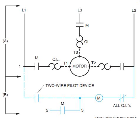
Fig. 3 Line diagram of starter shown in FIG. 2. (A) Line diagram showing
the simplicity of the power circuit for the line voltage starter; (B) completed
control wiring elementary style. Broken lines and motor are external field
wiring that completes the circuit.
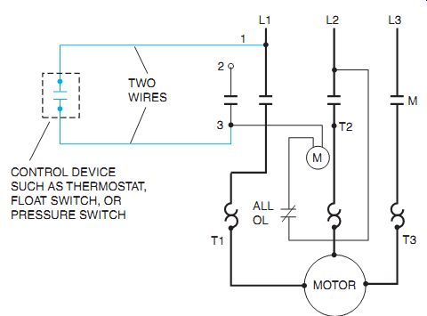
Fig. 4 Two wires lead from the pilot device to the starter. The phrases "no-voltage
release" and "two-wire control" should indicate to you that
an automatic pilot device, such as a limit switch or float switch, opens and
closes the control circuit through a single contact.
TWO-WIRE CONTROL
Two-wire control provides no-voltage release or low-voltage release. Two-wire control of a starter means that the starter drops out when there is a voltage failure and picks up as soon as the voltage returns. In FIG. 4, the pilot device is unaffected by the loss of voltage. Its contact remains closed, ready to carry current as soon as line voltage returns to normal. This form of control is used frequently to operate supply and exhaust blowers and fans.
Two-wire control is also shown in schematic form in FIG. 3(B). Two-wire control means that an operator does not have to be present to restart a machine following a voltage failure.
CAUTION: This type of restart can be a safety hazard to personnel and machinery. For example, materials in process may be damaged due to the sudden restart of machines on restoration of power. (Remember, power may return without warning.)
THREE-WIRE CONTROL
Three-wire control involves the use of a maintaining circuit. This method eliminates the need of the operator to press continuously on the push button to keep the coil energized.
The Maintaining Circuit
Recall from FIG. 1 that when pressure is released on the push button, it returns to its normally open position. The circuit to the coil is interrupted and it returns the relay contacts to their normal position. Normally, in starting a motor, it is desirable to energize the motor starter coil by pressing a button and then to keep the coil energized after the pressure is re leased from the button. Refer to the elementary control circuit diagram in FIG. 5.When the start button is pressed, coil M is energized across L1 and L2. This closes contact M to place a shunt circuit around 2-3, the start button. A parallel circuit is formed, with one circuit through push-button contacts 2-3 and one circuit through contact M. As a result, current will flow through the M coil. If pressure is removed from the start button, contacts 2-3 open. The other circuit through contact M will remain closed, supplying current to coil M and maintaining a starter closed position. Such a circuit is called a maintaining circuit, a sealing circuit, or a holding circuit.
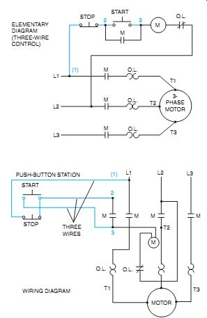
Fig. 5 Three wires lead from the pilot device to the starter. The phrases "no-voltage
protection" and "three-wire control" should indicate to the
electrician that the most common means of providing this type of control is
a start-stop push-button station.
No-Voltage Protection
Three-wire control providing no-voltage protection or low-voltage protection is also a basic and commonly used control circuit. In this type of circuit, three wires are used to control the contactor or starter.
Three-wire control of a starter means that the starter will drop out when there is a voltage failure but will not pick up automatically when volt age returns. The control circuit in FIG. 5 is completed through the stop button and also through a holding contact (2-3) on the starter.
When the starter drops out, the holding contact opens and breaks the control circuit until the start button is pressed to restart the motor.
The main distinction between the two types of control is that in no-voltage release (two-wire control), the coil circuit is maintained through the pilot switch contacts; in no-voltage protection (three-wire control), the circuit is maintained through a stop contact on the push button station and an auxiliary (maintaining) contact on the starter. The designations "two wire" and "three-wire" are used only because they describe the simplest applications of the two types of control. Actually, for more complicated circuits, there may be more wires leading from the pilot device to the starter. However, the principle of two-wire or three-wire control will still apply in these situations.
Three-wire control prevents the restarting of machinery when power is restored. In other words, an operator must press the start buttons to resume production when it is safe to do so.
In FIG. 3(B) contact 2-3 was not included in the two-wire circuit. This contact is the holding or maintaining contact, which is connected in a three-wire control circuit as shown in FIG. 5. It is sometimes shown smaller than power contacts.
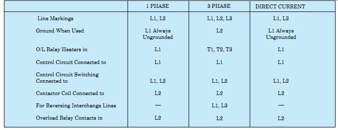
Table 1 Control and Power Connections-600 Volts or Less-Across-the-Line
Starters
Reviewing FIG. 5, it can be seen that when the start button is pressed, coil M is energized from line 1 (L1) through the normally closed stop push button, the depressed start button, the coil, and the overload control contacts to line 2 (L2).When coil M is energized, it closes all M contacts. The maintaining contact (2-3) holds the coil circuit when the start button is released. When the stop push button is pressed, the stop contact opens and the coil is de-energized. As a result, all M contacts are opened and the motor stops. In the event of a motor overload, excessive current is drawn from the line, causing the thermal heaters to overheat. When this happens, the normally closed overload relay control contacts are opened and the motor stops.
CONTROL AND POWER CONNECTIONS
The correct connections and component locations for line and wiring diagrams are indicated in Table 1. Compare the information given in the table with actual line diagrams to develop an ability to interpret the table quickly and use it correctly. For example, refer to FIG. 5 and the three-phase column of Table 1. Note that the control circuit switching is connected to line 1 (L1) and the contactor coil is connected to line 2 (L2).
TARGET TABLES
The phrase target table, or sequence chart, refers to a chart that lists the sequence of operation of identified contacts in a circuit. A target table is useful in interpreting circuit drawings and for simplifying troubleshooting.
One particular advantage of using a target table is shown in FIG. 6. Here, contacts on selector switches need not be drawn close together on the elementary diagram but can be spaced over the diagram if necessary. Broken lines should be drawn on the diagram to connect the various contacts of one switch; they represent an insulated mechanical connection, not to be confused with a wire connection.
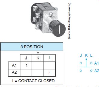
Fig. 6 Heavy-duty three-position selector switch, diagram symbol, and target
table.
Selector Switch Diagramming
FIG. 6 shows a typical, three-position se lector switch, its line diagram symbol, and a target table indicating the condition of each contact for each position of the selector switch.
The 1 (one) represents closed contacts. A small target table, such as that for a single two-circuit, double-contact switch, can be shown above the switch contact on the elementary diagram. Larger target tables should be shown to one side or below the line diagram.
The target table for the three-position selector switch shows that in the OFF position (arrow), no contacts are closed. In the J position, contact A1 is closed and A2 is open. In the L position, A2 is closed and A1 is open.
Drum Switch Diagramming
A drum switch consists of a set of moving contacts mounted on and insulated from a rotating shaft. The switch also has a set of stationary contacts that make and break contact with the moving contacts as the shaft is rotated, FIG. 7.
In the single-phase sample connection diagram, one motor rotation is shown with solid lines. The other direction is shown with broken lines, reversing one motor winding in relation to the other. A jumper should be added when this switch is used for single phase. The jumper is installed between 3 and 5.
The term drum switch is applied to cam switches as well. Drum switches provide a means for starting, stopping, and reversing AC single-phase, polyphase, or DC motors without overload protection, or where overload protection is provided by some other means. Drum switches may be used to carry the starting cur rent of a motor directly or they may be used to handle only the current for the pilot devices that control the main motor current.
In FIG. 8, the terminal markings (boxed by broken lines) indicate how the line and load are connected to the drum switch. The target table on the right shows which contacts are closed to reverse the three-phase motor and which contacts are closed to cause the motor to run forward.
Target tables are often used in complicated circuits to simplify the interpretation of the operation of large multicircuit drum switches.
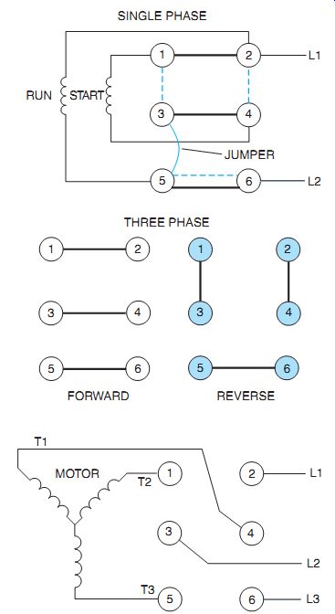
Fig. 7 Drum switch with cover removed; diagrams show switch connections to
single-phase and three-phase motors.

Fig. 8 A target table is used to assist in the interpretation of drum switch
operation where a three-phase or a single-phase motor is reversed by interchanging
two motor leads.
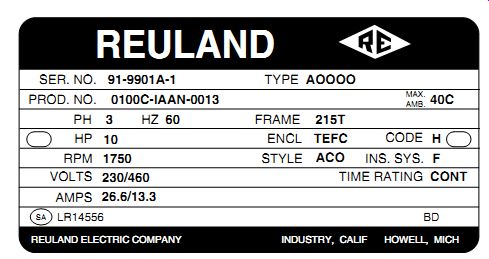
Fig. 9 Standard three-phase motor nameplate.
MOTOR NAMEPLATE DATA AND WIRING INTERPRETATION
FIG. 9 shows a typical motor nameplate for a standard three-phase, nine-lead motor.
Serial Number and Product Number All manufacturers must identify a specific motor somehow. The serial number is a common way to identify a specific motor. This number is unique to a specific motor and is the most common way to identify special equipment made to a specific customer's order. However, there are manufacturers building very large lots of motors for sale through warehouse distribution. Often a computerized product number or catalog model number is used for identification. This type of number will identify a bill of materials for construction, but not a specific motor such as the serial number.
Type and Style
These various characters are unique to a manufacturer. In general, each manufacturer has an individual set of designations. For example, a type of motor may be specified for a particular application, have normal starting torque, normal starting current, and normal slip. A mechanical characteristic is that the motor is drip proof.
Max. Amb.
This is the maximum temperature the motor should operate at safely under full load. The nameplate shown in FIG. 9 gives the motor frame number 215T, which refers to the frame dimension given on the manufacturer's detailed dimension sheets.
HP and Code
The horsepower (hp) rating given on the nameplate refers to the output of the motor, as measured by mechanical means. The code letter on the nameplate indicates the locked rotor kVA input per horsepower as shown in NEMA standards. This code letter shall be used for determining the branch-circuit short-circuit protection and ground-fault protection from applicable tables in the NEC®.
Time Rating
This is sometimes referred to as DUTY. Usually a time reference is used, such as 5, 15, 30, 60 minute duty, or CONT for continuous operation. Occasionally an application name may be used, such as "extractor duty" for a laundry ex tractor. RPM on the nameplate refers to the speed of the motor in revolutions per minute.
The current in amperes drawn by the motor is listed under AMPS and varies according to the voltage system to which the motor is connected.
Motors draw half as much current on high volt ages as they do on low voltages. However, the same amount of power is used for either high or low-voltage connections (P = E x I). Low current connections mean that smaller wire sizes, conduits, feeders, and switch gear can be used. If available, connection to high voltages will mean a financial savings in wiring materials and less wasted electrical energy due to de creased voltage drop in the circuits. The motor starter voltage must be equal to the supply volt age (except for separate control, Unit 17), and the overload heaters must be rated for the proper current value.
In FIG. 9, the volts indication refers to motor terminal connections 230 volts; the HIGH volts, 460.
Phase and Hertz
Ph refers to phase, such as three-phase voltage. HZ means the voltage hertz, or voltage frequency. The most common electrical service in North America is 60 Hz.
Insulation System (INS SYS) This is an indication of the materials used for insulating the motor winding. It will give an indication of the temperature capabilities and environmental protection of the wire and varnish used.
Additional Data
There are often additional plates on a motor.
The connection plate is used to identify the various reconnections of the motor leads of dual voltage and multispeed motors. Besides motor winding connections, there may be a space heater, temperature sensor, lubrication, bearings, lifting data, and safety approval plates. Motor space heaters are an optional item used to keep motors dry in humid climates. See FIG. 10.
Motor connection plates, or data, are sometimes found inside the motor terminal connection box cover. Such information is shown in FIG. 11.
For a high-voltage connection, the nameplate shows that motor lead terminals 4 and 7 are connected, as are 5 and 8, and 6 and 9. The connections are insulated from each other in the motor terminal connection box. The three remaining leads (1, 2, and 3) are connected to three-phase supply lines L1, L2, and L3. Actually, this connection is to the load side of the starter terminals (T1, T2, and T3).
The nameplates for some motors include a service factor reference. The service factor of a general-purpose motor is an allowable overload.
The amount of allowable overload is indicated by a multiplier. When this multiplier is applied to the normal horsepower rating, the permissible loading is indicated.
In keeping with a greater awareness of energy conservation, many motor manufacturers indicate a percentage efficiency value on the nameplates of selected motors. The nameplate shown in FIG. 12 contains both an efficiency rating (94.1 percent) and a service factor value (1.15).
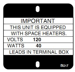
Fig. 10 Motor space heater nameplate.

Fig. 11 Typical nameplate of motor connections.
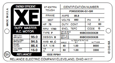
Fig. 12
Nameplate for an energy efficient motor.
MOTOR POWER AND GREATER EFFICIENCY
The only power that the electric motor consumes is used up in losses of about 6 to 7 percent.
Major losses are copper losses (I2R), iron losses (eddy currents and hysteresis), and windage. A common error is that motors use over 60 per cent of all electrical power consumed, but they only convert and deliver it to mechanical loads.
The much greater amount of energy is used up by the driven load.
Mechanical equipment experiences far greater losses than electric motors. Greater energy efficiency can be achieved by improving motors, using more efficient motors, and by designing and using more efficient mechanical equipment. For example, a motor-pump shaft seal with a carbon disc-to-flat metal ring seal, instead of the common shaft compression seal, creates drag. Throttle valves and narrow pipes can waste huge amounts of power; so can inefficient pumps. Proper lubrication to driven machines makes them easier on the motor. Of course a motor that is larger than necessary wastes away still more energy. We not only save energy, we also get better performance with some attention to driven equipment.
Using an adjustable speed drive is one of the fastest ways to save energy, but it must be a good one. Adjustable speed drives are some times hard to select. Although upgrading motors and the inefficient equipment that they run involves major changes for businesses, the energy savings will make the effort worth while.
THREE-PHASE, DUAL-VOLTAGE MOTOR CONNECTIONS
FIG. 13 shows a recommended method of determining the three-phase motor terminal connections in the event that the motor name plate is inaccessible, destroyed, or lost when the motor is installed. Test equipment is used to determine the unknown internal wiring connections of the motor, either star or delta. A continuity test will find one group of three common leads. For example, such a test will establish the center of the star high-voltage connection (at T7, T8, and T9) in FIG. 13, upper left. There should be only one group of three motor leads common to each other for a star-connected motor, and three groups of three leads common to each other for a delta, internally connected motor (T1-T4-T9, T2-T5-T7, T3-T6-T8).
SINGLE-PHASE, DUAL-VOLTAGE MOTOR CONNECTIONS
The connections for dual-voltage, single phase AC motors are shown in FIG. 14.
For low-voltage operation, the stator coils are connected in parallel; for high-voltage operation, they are connected in series. The instantaneous current direction is indicated by arrows at the motor coils. In general, starting windings are factory connected to the terminal screws for 120 volts.
All external wiring motor leads are located in the motor terminal connection or conduit box.
REVERSING A SINGLE-PHASE MOTOR WITH A DRUM SWITCH
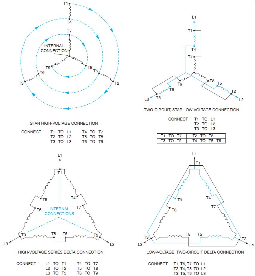
Fig. 13 Three-phase motor terminal connections.
To reverse a single-phase AC motor, either the starting or running windings connections (but not both) must be reversed on the line. In this example it will be assumed that the run winding leads of the motor are labeled T1 and T2, and the start winding leads are labeled T5 and T8. The drum switch previously discussed will be used in this illustration, FIG. 15.
The circuit is connected as shown in FIG. 16. A jumper is connected between terminals 3 and 5 of the drum switch. When the switch is in the off position no connection is made across the terminals of the switch. Although terminal T5 of the motor is connected directly to the terminal 2 of the drum switch and the neutral conductor, there is no connection between terminals 5 and 6 of the drum switch. Line 1 is, therefore, not connected to the start winding.
When the drum switch is moved to the for ward position, connection is made as shown in FIG. 17.Terminal T8 of the start winding is connected to Line 1 and T5 is connected to the neutral conductor. Terminal T1 of the run winding is connected to Line 1 and terminal T2 is connected to neutral.
When the drum switch is moved to the re verse position, connection is made as shown in FIG. 18. Terminal T8 of the start winding is still connected to Line 1 and T5 is still connected to the neutral conductor. Terminal T1 of the run winding, however is now connected to neutral and T2 is now connected to Line 1. Note that the start winding connections remain the same regardless of the position of the drum switch, but the run windings change between forward and reverse.

Fig. 14 Single-phase, dual-voltage motors.
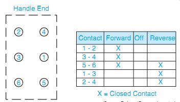
Fig. 15
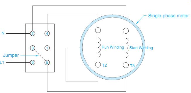
Fig. 16 Single-phase motor connected to a drum switch.
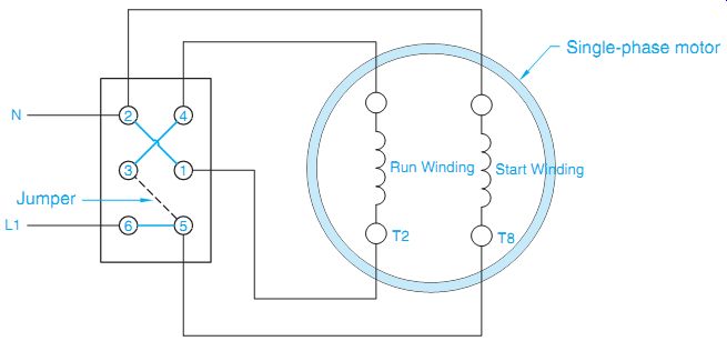
Fig. 17 The drum switch is moved to the forward position.

Fig. 18 The drum switch is moved to the reverse position.
QUIZ:
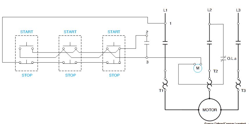
1. In which diagram do the physical locations of the wiring and the devices match the drawing?
2. Which diagram conveys as much information as possible with the least amount of confusion?
3. Why is it not necessary to show the armature and crossbar or the overload reset mechanism in a wiring diagram?
4. Which control wiring scheme can cause damage to industrial production or processing equipment with the sudden restart of machines on restoration of the power?
5. In developing line or wiring diagrams, in which lines should the overload relays be placed for three-phase motor starters?
6. In which control circuit wire are the overload relay contacts connected?
7. The control circuit is connected to which lines for a three-phase motor starter?
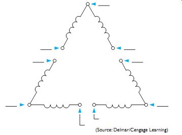
8. Identify the terminal markings for the delta-wound motor shown in FIG. 19.
9. The contactor coil is connected to which line of a three-phase contactor?
10. What does the "X" or "1" mean on a target table?
11. A motor nameplate reads 230/460 volts, 30-15 amperes. When connected to a 460-volt supply, how much current will the motor draw fully loaded?
12. To what does the code letter on a motor nameplate refer?
13. Draw an elementary line diagram of the control circuit from the wiring diagram shown in FIG. 20. Exclude power or motor circuit wiring.
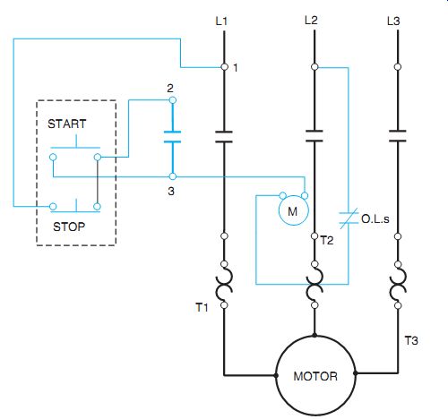
14. Draw a line diagram of the control circuit shown in FIG. 21. (Exclude power or motor circuit wiring.)
