AMAZON multi-meters discounts AMAZON oscilloscope discounts
Goals:
• Identify common electrical symbols used in motor control diagrams.
• Use electrical symbols in drawing schematic and wiring diagrams.
• Draw and define supplementary contact symbols.
If the directions for wiring electrical equipment are written without the use of diagrams, or if diagrams are used but must show each device as it actually appears, then the work and time involved both in preparing the directions and in installing the equipment will be very expensive. Therefore, symbols--a form of pictorial shorthand--are used rather than pictures of electrical equipment to show how separate pieces of electrical equipment are connected in a circuit. Because the symbols may not be similar to the physical appearance of the devices they represent, many symbols must be memorized.
Unfortunately, there is no actual standard used for motor control symbols. Different manufacturers and companies often use their own set of symbols for their in-house schematics.
Also, schematics drawn in other countries may use an entirely different set of symbols to rep resent different control components. Although symbols can vary from one manufacturer to another, or from one country to another, once you have learned to interpret circuit logic, it is generally possible to determine what the different symbols represent by the way they are used in the schematic. The most standardized set of symbols in the United States is provided by the NEMA. It is these symbols that will be discussed in this unit.
Push Buttons:
One of the most used symbols in control schematics is the push button. Push buttons can be shown as normally open or normally closed, FIG. 1. Most are momentary contact devices in that they make or break connection only as long as pressure is applied to them.
When the pressure is removed, they return to their normal position. Push buttons contain both movable and stationary contacts. The stationary contacts are connected to the terminal screws. The normally open push button is characterized by drawing the movable contact above and not touching the stationary contacts.
Because the movable contact does not touch the stationary contacts, there is an open circuit and current cannot flow from one stationary contact to the other. The way the symbol is drawn assumes that pressure will be applied to the movable contact. When the button is pressed, the movable contact moves downward and bridges the two stationary contacts to complete a circuit, FIG. 2. When pressure is removed from the button, a spring returns the movable contact to its original position.
The normally closed push button symbol is characterized by drawing the movable contact below and touching the two stationary contacts.
Because the movable contact touches the two stationary contacts, a complete circuit exists and current can flow from one stationary contact to the other. If pressure is applied to the button, the movable contact will move away from the two stationary contacts and open the circuit.
Another very common push button found throughout industry is the double-acting push button, FIG. 3. Double-acting push buttons contain both normally open and normally closed contacts. When connecting these push buttons in a circuit, you must make certain to connect the wires to the correct set of contacts.

Fig. 1 NEMA standard push-button symbols.
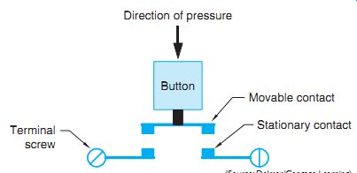
Fig. 2 The movable contact bridges the stationary contacts when the button
is pressed.
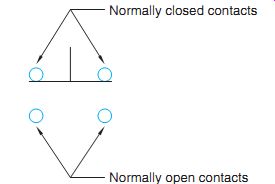
Fig. 3 Double-acting push button.
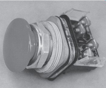
Fig. 4 The double-acting push button has four screw terminals.
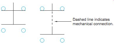
Fig. 5 Other symbols used to represent double acting push buttons.
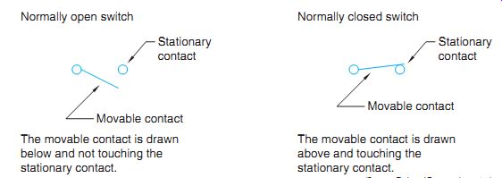
Fig. 6 Normally open and normally closed switches.
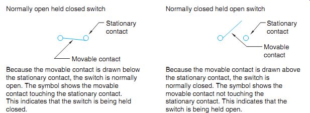
Fig. 7 Normally open held closed and normally closed held open switches.
A typical double-acting push button is shown in FIG. 4. Note that the double-acting push button has four terminal screws. The symbol for a double-acting push button can be drawn in different ways, FIG. 5. The symbol on the left is drawn with two movable contacts connected by one common shaft. When the button is pressed, the top movable contact breaks away from the top two stationary contacts and the bottom movable contact bridges the bottom two stationary contacts to complete the circuit.
The symbol on the right is very similar in that it also shows two movable contacts. The right-hand symbol, however, connects the two push-button symbols with a dashed line. When components are shown connected by a dashed line in a schematic diagram, it indicates that the components are mechanically connected. If one is pressed, all that are connected by the dashed line are pressed. This is a very common method of showing several sets of push-button contacts that are actually controlled by one button.
Switch Symbols
Switch symbols are employed to represent many common control-sensing devices. There are four basic symbols: normally open (NO), normally closed (NC), normally open held closed (NOHC), and normally closed held open (NCHO). To understand how these switches are drawn, it is necessary to begin with how normally open and normally closed switches are drawn, FIG. 6.
Normally open switches are drawn with the movable contact below and not touching the stationary contact. Normally closed switches are drawn with the movable contact above and touching the stationary contact.
The normally open held closed and normally closed held open switches are shown in FIG. 7. Note that the movable contact of the normally open held closed switch is drawn below the stationary contact. The fact that the movable contact is drawn below the stationary contact indicates that the switch is normally open. Because the movable contact is touching the stationary contact, however, a complete circuit does exist because something is holding the contact closed. A very good example of this type switch is the low-pressure switch found in many air-conditioning circuits, FIG. 8. The low-pressure switch is being held closed by the refrigerant in the sealed system. If the refrigerant should leak out, the pressure will drop low enough to permit the contact to return to its normal open position. This would open the circuit and de-energize coil C, causing both C contacts to open and disconnect the compressor from the power line. Although the schematic indicates that the switch is closed during normal operation, it would have to be connected as an open switch when it is wired into the circuit.
The normally closed held open switch is shown open in FIG. 7. Although the switch is shown open, it is actually a normally closed switch because the movable contact is drawn above the stationary contact, indicating that something is holding the switch open. A good example of how this type switch can be used is shown in FIG. 9. This circuit is a low-water warning circuit for a steam boiler. The float switch is held open by the water in the boiler. If the water level should drop sufficiently, the contacts will close and energize a buzzer and warning light.
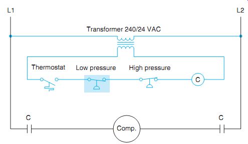
Fig. 8 If system pressure should drop below a certain value, the normally
open held closed low-pressure switch will open and de-energize coil C.
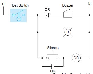
Fig. 9 Low-water warning circuit .
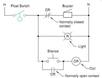
Fig. 10 Circuit with labeled components.
Basic Schematics
To understand the operation of the circuit shown in FIG. 9, you must understand some basic rules concerning schematic or ladder diagrams.
1. Schematics show components in their electrical sequence without regard for physical location. The schematic in FIG. 9 has been redrawn in FIG. 10. Labels have been added, and the schematic shows a coil labeled CR and one normally open and one normally closed contact labeled CR. All of these components are physically located on control relay CR.
2. Schematics are always drawn to show components in their de-energized or off state.
3. Any contact that has the same label or number as a coil is controlled by that coil. In this example, both CR contacts are controlled by the CR coil.
4. When a coil energizes, all contacts con trolled by it change position. Any normally open contacts will close and normally closed contacts will open. When the coil is de-energized, the contacts will return to their normal state.
Referring to FIG. 10, if the water level should drop far enough, the float switch will close and complete a circuit through the normally closed contact to the buzzer and to the warning light connected in parallel with the buzzer. At this time both the buzzer and warning light are turned on. If the silence push button is pressed, the CR coil will energize and both CR contacts will change position. The normally closed contact will open and turn off the buzzer.
The warning light, however, will remain on as long as the low water level exists. The normally open CR contact connected in parallel with the silence push button will close. This contact is generally referred to as a holding, sealing, or maintaining contact. Its function is to maintain a current path to the coil when the push button returns to its normal open position. The circuit will remain in this state until the water level becomes high enough to reopen the float switch.
When the float switch opens, the warning light and CR coil will turn off. The circuit is now back in it original de-energized state.
SENSING DEVICES
Motor control circuits depend on sensing de vices to determine what conditions are occur ring. They act very much like the senses of the body. The brain is the control center of the body.
It depends on input information such as sight, touch, smell, and hearing to determine what is happening around it. Control systems are very similar in that they depend on such devices as temperature switches, float switches, limit switches, flow switches, and so on to know the conditions that exist in the circuit. These sensing devices will be covered in greater detail later in the text. The four basic types of switches are used in conjunction with other symbols to represent some of these different kinds of sensing switches.
Limit Switches
Limit switches are drawn by adding a wedge to one of the four basic switches, FIG. 11. The wedge represents the bumper arm. Common industrial limit switches are shown in FIG. 12.
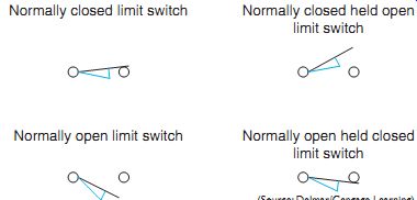
Fig. 11 Limit switches.
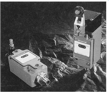
Fig. 12 Typical industrial limit switches.
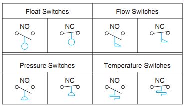
Fig. 13 Schematic symbols for sensing switches.
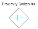
Fig. 14 Special symbols are often used for sensing devices that do not have
a standard symbol.
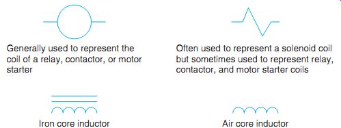
Fig. 15 Common coil symbols.
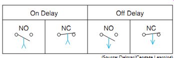
Fig. 16 Timed contact symbols.
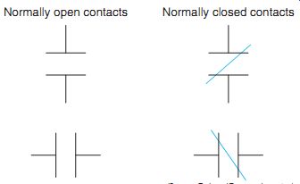
Fig. 17 Normally open and normally closed contact symbols.
Float, Pressure, Flow, and Temperature Switches
The symbol for a float switch illustrates a ball float. It is drawn by adding a circle to a line, FIG. 13. The flag symbol of the flow switch represents the paddle that senses movement.
The flow switch symbol is used for both liquid and air-flow switches. The symbol for a pressure switch is a half circle connected to a line. The flat part of the semicircle represents a diaphragm.
The symbol for a temperature switch represents a bimetal helix. The helix will contract and expand with a change of temperature. It should be noted that any of these symbols can be used with any of the four basic switches.
There are many other types of sensing switches that do not have a standard symbol. Some of these are photo switches, proximity switches, sonic switches, Hall Effect switches, and others. Some manufacturers will employ some special type of symbol and label the symbol to indicate the type of switch. An example of this is shown in FIG. 14.
Coils
The most common coil symbol used in schematic diagrams is the circle. The reason for this is that letters and/or numbers are written in the circle to identify the coil. Contacts controlled by the coil are given the same number. Several standard coil symbols are shown in FIG. 15.
Timed Contacts
Timed contacts are either normally open or normally closed. They are not drawn as normally open held closed or normally closed held open.
There are two basic types of timers, on delay and off delay. Timed contact symbols use an arrow to point in the direction that the contact will move at the end of the time cycle. Timers will be discussed in detail in a later unit. Standard timed contact symbols are shown in FIG. 16.
Contact Symbols
Another very common symbol used on control schematics is the contact symbol. The symbol is two parallel lines connected by wires, FIG. 17.
The normally open contacts are drawn to represent an open connection. The normally closed contact symbol is the same as the normally open symbol with the addition of a diagonal line drawn through the contacts. The diagonal line indicates that a complete current path exists.
Other Symbols
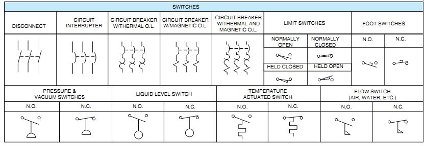
Fig. 18 Standard wiring diagram symbols.
Not only are there NEMA standard symbols for coils and contacts, but there are also symbols for transformers, motors, capacitors, and special types of switches. A chart of both common control and electrical symbols is shown in FIG. 18.
EXPLANATION OF COMMON SYMBOLS
The control circuit line diagram of FIG. 19 shows the symbols of each device used in the circuit. The diagram indicates the function of each device. The push-button station wiring diagram on the right of FIG. 19 represents the physical control station and shows the relative position of each device, the internal wiring, and the connections with the motor starter.
Refer to FIG. 18. The disconnect switch shown is used to disconnect live equipment from the line voltage. This action is usually done with the equipment unloaded. The load may be interrupted by using contactors, motor starters, or circuit interrupters such as circuit breakers.
Machine operators often find that a foot switch is provided. The use of the foot switch frees the operator's hands. The switch mechanism is usually a heavy-duty, double-break, normally open or closed switch in a rugged en closure with a broad mushroom-like metallic pedal or foot operator. This type of switch may be connected by a portable cord or wired in solid, in a stationary position near the machine to be controlled.
The wobble stick push button is controlled by a stem that can be operated from any direction.
It is so constructed for fast and easy access by a production machine operator.
The maintained contact push buttons are mechanically held in the selected position.
The push to test pilot light is used to ensure that the lamp and circuit are OK. In the push position it is placed across the control voltage.
Otherwise, it may be connected so that it will indicate when a machine or pump motor is on or off.
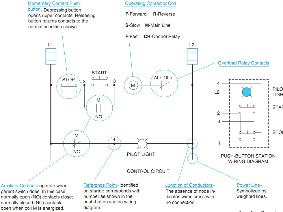
Fig. 19 Control circuit components.
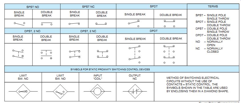
Fig. 20 Supplementary contact symbols.
The timed contacts are described in Unit 9, "Timing Relays. "Note that there is a time delay in the contact action when the relay coil is energized (on delay). In a different contact arrangement, there is also a time delay when the coil is de-energized (off delay).
A shunt coil is connected with the full voltage applied. A series coil is connected in series with a load or the full current.
In drawing wiring diagrams, it is not an accepted practice to "jump" a wire. Wires are shown as crossing each other and, unless specified otherwise, are not connected. If a wire is to be connected, a quick method is to show it with a connection node or dot.
Mechanical connections are shown with straight broken lines (they are insulated, non-current carrying parts). One example is when two contacts are operated at the same time on a push button.
The speed plugging and antiplugging switch symbol will be shown in use later in the text.
FIG. 20 defines abbreviations commonly used in wiring prints and specifications. The symbols further illustrate descriptions of the abbreviation.
QUIZ
1. Identify the following symbols.
2. Electrical symbols usually conform to which standard?
3. What do the following abbreviations stand for?
a. SPST d. DPDT
b. SPDT e. NO
c. DPST f. NC
4. Single-pole and double-pole switch symbols are shown as
a. single break
b. double break
c. NO and NC
d. all of the above
5. The symbol shown is
a. polarized capacitor
b. normally closed switch
c. normally open held closed switch
d. normally open contact
6. The symbol shown is
a. normally closed float switch
b. normally open held closed float switch
c. normally open float switch
d. normally closed held open float switch
7. The symbol shown is
a. iron core transformer
b. auto transformer
c. current transformer
d. air core transformer
8. The symbol shown is
a. normally open pressure switch
b. normally open flow switch
c. normally open float switch
d. normally open temperature switch
9. The symbol shown is
a. double-acting push button
b. two-position selector switch
c. three-position selector switch
d. maintained contact pushbutton
10. If you were installing the circuit in FIG. 9,what type of push button would you use for the silence button?
a. Normally closed
b. Normally open
11. Referring to the circuit in FIG. 9, should the float switch be connected as a normally open or normally closed switch?
12. Referring to the circuit in FIG. 9,what circuit component controls the actions of the two CR contacts?
13. Why is a circle most often used to represent a coil in a motor control schematic?
14. When reading a schematic diagram, are the control components shown as they should be when the machine is turned off or de-energized, or are they shown as they should be when the machine is in operation?