AMAZON multi-meters discounts AMAZON oscilloscope discounts
GOALS:
- List factors that determine the speed of the rotating magnetic field.
- Determine synchronous speed for different numbers of poles and frequency.
- Discuss how direct current is converted to alternating current.
- Discuss the characteristics of insulated gate bipolar transistors.
- Discuss how SCRs can be used to change DC voltage into AC voltage.
- List differences between inverter-rated motors and non-inverter-rated motors.
Although DC motors are still used in many industries, they are being replaced by variable frequency drives controlling squirrel cage induction motors. The advantage of a DC motor compared with an AC motor is that the speed of the DC motor can be controlled. Although the wound rotor motor does permit some degree of speed control, it does not have the torque characteristics of a DC motor. DC motors can develop maximum torque at zero rpm. Variable frequency drives can give the same speed and torque characteristics to AC squirrel cage induction motors. A variable-frequency drive and AC squirrel cage motor are less expensive to purchase than a comparable DC drive and DC motor. Variable-frequency drives and AC motors have less downtime and maintenance problems than DC drives and DC motors.
VARIABLE-FREQUENCY DRIVE OPERATING PRINCIPLES
The operating principle of all AC three-phase motors is the rotating magnetic field. The speed of the rotating field is called synchronous speed and is controlled by two factors:
- The number of stator poles per phase
- The frequency of the applied voltage
The chart shown in ill. 1 lists the synchronous speed for different numbers of poles at different frequencies. Variable-frequency drives control motor speed by controlling the frequency of the power supplied to the motor.
Basic Construction of a Variable-Frequency Drive
Most variable-frequency drives operate by first changing the AC voltage into DC and then changing it back to AC at the desired frequency.
There are several methods used to change the DC voltage back into AC. The method employed is determined by the manufacturer, age of the equipment, and the size motor that the drive must control. Variable-frequency drives intended to control the speed of motors up to 500 hp generally employ transistors. In the circuit shown in ill. 2, a single-phase bridge changes the alternating current into direct current. The bridge rectifier uses two SCRs and two diodes. The SCRs permit the output voltage of the rectifier to be controlled. As the frequency decreases, the SCRs fire later in the cycle and lower the output voltage to the transistors. As the frequency of the voltage is reduced, the inductive reactance of the motor stator winding is also reduced. The voltage applied to the motor must also be reduced to prevent the motor from being damaged by excessive current. A choke coil and capacitor bank are used to filter the output voltage before transistors Q1 through Q6 change the DC volt age back into AC. An electronic control unit's connected to the bases of transistor Q1 through Q6. The control unit converts the DC voltage back into three-phase alternating current by turning transistors on or off at the proper time and in the proper sequence. Assume, for example, that transistors Q1 and Q4 are switched on at the same time. This permits stator winding T1 to be connected to a positive voltage and T2 to be connected to a negative voltage. Current can flow through Q4 to T2, through the motor stator winding and through T1 to Q1.
Now assume that transistors Q1 and Q4 are switched off and transistors Q3 and Q6 are switched on. Current will now flow through Q6 to stator winding T3, through the motor to T2, and through Q3 to the positive of the power supply.
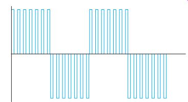
Because the transistors are turned completely on or completely off, the waveform produced is a square wave instead of a sine wave, ill. 3. Induction motors will operate on a square wave without a great deal of problems.
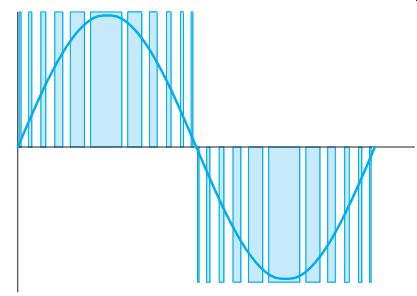
Some manufacturers design units that will produce a stepped waveform as shown in ill. 4. The stepped waveform is used because it closely approximates a sine wave.
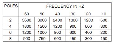
ill. 1 Speed in rpm for motors with different numbers of poles per phase at
different frequencies.
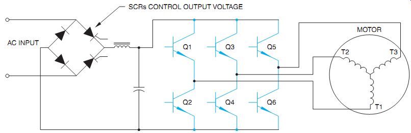
ill. 2 Basic schematic of a variable-frequency drive.
Some Related Problems
The circuit illustrated in ill. 2 uses SCRs in the power supply and junction transistors in the output stage. SCR power supplies control the output voltage by chopping the incoming waveform. This can cause harmonics on the line that cause overheating of transformers and motors and can cause fuses to blow and circuit breakers to trip. When bipolar junction transistors are employed as switches, they are generally driven into saturation by supplying them with an excessive amount of base-emitter current. Saturating the transistor causes the collector-emitter voltage to drop to between 0.04 and 0.03 volt.
This small voltage drop allows the transistor to control large amounts of current without being destroyed. When a transistor is driven into saturation, however, it cannot recover or turn off as quickly as normal. This greatly limits the frequency response of the transistor.
Insulated Gate Bipolar Transistor Many transistor-controlled variable drives now employ a special type of transistor called an insulated gate bipolar transistor (IGBT).
IGBTs have an insulated gate very similar to some types of field effect transistors (FETs).
Because the gate is insulated, it has a very high impedance. The IGBT is a voltage-controlled device, not a current-controlled device. This gives it the ability to turn off very quickly.
IGBTs can be driven into saturation to provide a very low voltage drop between the emitter and collector, but they don't suffer from the slow recovery time of common junction transistors. The schematic symbol for an IGBT is shown in ill. 5.
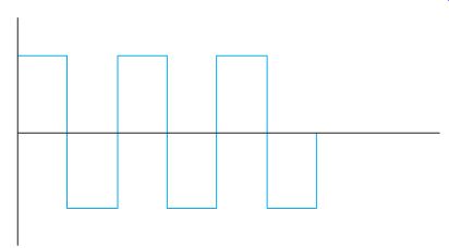
ill. 3 Square wave voltage waveform.
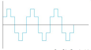
ill. 4 A stepped waveform approximates a sine wave.

ill. 5 Schematic symbol for an insulated gate bipolar transistor.
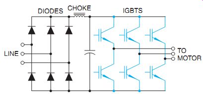
ill. 6 Variable-frequency drives using IGBTs generally use diodes in the rectifier
instead of SCRs.
ill. 7 Pulse width modulation is accomplished by turning the voltage on and off several times during each half cycle.
ill. 8 The speed of the IGBT can produce a stepped wave that's similar to
a sine wave.
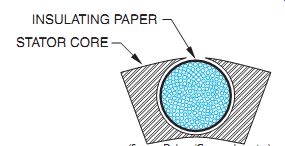
ill. 9 Insulating paper is between the windings and the stator frame.
Drives using IGBTs generally use diodes to rectify the AC voltage into DC, not SCRs, ill. 6.The three-phase rectifier supplies a constant DC voltage to the transistors. The output voltage to the motor is controlled by pulse width modulation (PWM). PWM is accomplished by turning the transistor on and off several times during each half cycle, ill. 7. The output voltage is an average of the peak or maximum voltage and the amount of time the transistor is turned on or off. Assume that 480 volts, three-phase alternating current is rectified to direct current and filtered. The DC voltage applied to the IGBTs is approximately 630 volts.
The output voltage to the motor is controlled by the switching of the transistors. Assume that the transistor is on for 10 microseconds and off for 20 microseconds. In this example the transistor is on for one-third of the time and off for two thirds of the time. The voltage applied to the motor would be 210 volts (630/3). The speed at which IGBTs can operate permits pulse width modulation to produce a stepped wave that's very similar to a standard sine wave, ill. 8.
Advantages and Disadvantages of IGBT Drives
A great advantage of drives using IGBTs is that SCRs are generally not used in the power supply, and this greatly reduces problems with line harmonics. The greatest disadvantage is that the fast switching rate of the transistors can cause voltage spikes in the range of 1600 volts to be applied to the motor. These voltage spikes can destroy some motors. Line length from the drive to the motor is of great concern with drives using IGBTs. The shorter the line length the better.
Inverter-Rated Motors
Due to the problem of excessive voltage spikes caused by IGBT drives, some manufacturers produce a motor that's "inverter rated." These motors are specifically designed to be operated by variable-frequency drives. They differ from standard motors in several ways:
1. Many inverter rater motors contain a separate blower to provide continuous cooling for the motor regardless of the speed.
Many motors use a fan connected to the motor shaft to help draw air through the motor. When the motor speed is reduced, the fan cannot maintain sufficient airflow to cool the motor.
2. Inverter-rated motors generally have insulating paper between the windings and the stator core, ill. 9. The high-voltage spikes produce high currents that produce a high magnetic field. This increased magnetic field causes the motor windings to move. This movement can eventually cause the insulation to wear off the wire and produce a grounded motor winding.
3. Inverter-rated motors generally have phase paper added to the terminal leads.
Phase paper is insulating paper added to the terminal leads that exit the motor. The high-voltage spikes affect the beginning lead of a coil much more than the wire inside the coil. The coil is an inductor that naturally opposes a change of current.
Most of the insulation stress caused by high-voltage spikes occurs at the beginning of a winding.
4. The magnet wire used in the construction of the motor windings has a higher rated insulation than other motors.
5. The case size is larger than most three phase motors because of the added insulating paper between the windings and the stator core. Also, a larger case size helps cool the motor by providing a larger surface area for the dissipation of heat.
Variable-Frequency Drives Using SCRs and GTOs
Variable-frequency drives intended to control motors over 500 hp generally use SCRs or gate turn-off devices (GTOs). GTOs are similar to SCRs except that conduction through the GTO can be stopped by applying a negative voltage-negative with respect to the cathode-to the gate. SCRs and GTOs are thyristors and have the ability to handle a greater amount of current than transistors. An example of a single-phase circuit used to convert DC voltage to AC voltage with SCRs is shown in ill. 10. In this circuit, the SCRs are connected to a control unit that controls the sequence and rate at which the SCRs are gated on. The circuit's constructed so that SCRs A and A_ are gated on at the same time and SCRs B and B_ are gated on at the same time. Inductors L1 and L2 are used for filtering and wave shaping. Diodes D1 through D4 are clamping diodes and are used to prevent the output volt age from becoming excessive. Capacitor C1 is used to turn one set of SCRs off when the other set is gated on. This capacitor must be a true AC capacitor because it will be charged to the alternate polarity each half cycle. In a converter intended to handle large amounts of power, capacitor C1 will be a bank of capacitors. To understand the operation of the circuit, assume that SCRs A and A_ are gated on at the same time. Current will flow through the circuit as shown in ill. 11. Notice the direction of current flow through the load and that capacitor C1 has been charged to the polarity shown. When an SCR is gated on, it can only be turned off by permitting the cur rent flow through the anode-cathode section to drop below a certain level called the holding current level. The SCR won't turn off as long as the current continues to flow through the anode-cathode.
Now assume that SCRs B and B_ are turned on. Because SCRs A and A_ are still turned on, two current paths now exist through the circuit.
The positive charge on capacitor C1, however, causes the negative electrons to see an easier path. The current will rush to charge the capacitor to the opposite polarity, stopping the cur rent flowing through SCRs A and A_ permitting them to turn off. The current now flows through SCRs B and B_ and charges the capacitor to the opposite polarity, ill. 12. Notice that the current now flows through the load in the opposite direction, which produces alternating cur rent across the load.
To produce the next half cycle of alternating current, SCRs A and A_ are gated on again. The positively charged side of the capacitor will now cause the current to stop flowing through SCRs B and B_, permitting them to turn off. The current again flows through the load in the direction indicated in ill. 11. The frequency of the circuit's determined by the rate at which the SCRs are gated on.
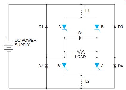
ill. 10 Changing DC to AC using SCRs.
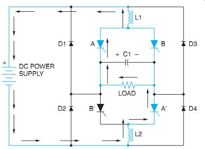
ill. 11 Current flows through SCRs A and A_.
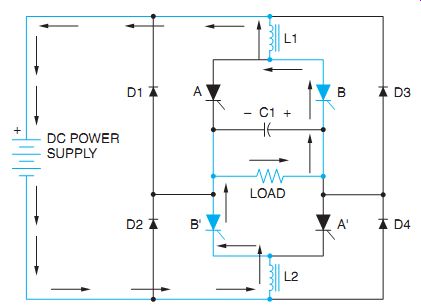
ill. 12 Current flows through SCRs B and B_.
Features of Variable-Frequency Control
Although the primary purpose of a variable frequency drive is to provide speed control for an AC motor, most drives provide functions that other types of controls don't. Many variable frequency drives can provide the low-speed torque characteristic that's so desirable in DC motors. It is this feature that permits AC squirrel cage motors to replace DC motors for many applications.
Many variable-frequency drives also provide current limit and automatic speed regulation for the motor. Current limit's generally accomplished by connecting current transformers to the input of the drive and sensing the increase in current as load is added. Speed regulation is accomplished by sensing the speed of the motor and feeding this information back to the drive.
Another feature of variable-frequency drives is acceleration and deceleration control, some times called "ramping." Ramping is used to accelerate or decelerate a motor over some period of time. Ramping permits the motor to bring the load up to speed slowly as opposed to simply connecting the motor directly to the line.
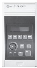
Even if the speed control is set in the maximum position when the start button is pressed, ramping permits the motor to accelerate the load from zero to its maximum rpm over several seconds. This feature can be a real advantage for some types of loads, especially gear drive loads. In some units the amount of acceleration and deceleration time can be adjusted by set ting potentiometers on the main control board, ill. 13. Other units are completely con trolled digitally and the amount of acceleration and deceleration time is programmed into the computer memory.
ill. 13 Adjustments are made with potentiometers on some units.
Some other adjustments that can usually be set by changing potentiometers or programming the unit are as follows.
Current Limit: This control sets the maximum amount of current the drive is per mitted to deliver to the motor.
Volts per Hertz: This sets the ratio by which the voltage increases as frequency increases or decreases as frequency decreases.
Maximum Hz: This control sets the maxi mum speed of the motor. Most motors are intended to operate between 0 and 60 Hz, but some drives permit the output frequency to be set above 60 Hz, which would permit the motor to operate at higher than normal speed. The maximum hertz control can also be set to limit the output frequency to a value less than 60 Hz, which would limit the motor speed to a value less than normal.
Minimum Hz: This sets the minimum speed the motor is permitted to run.
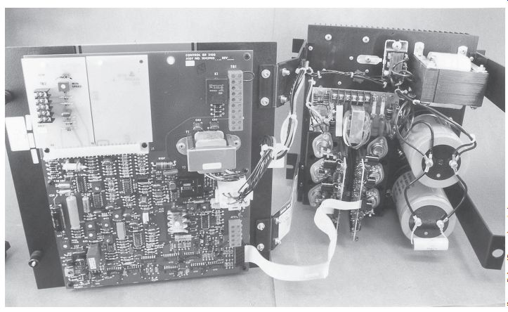
Some variable-frequency drives permit adjustment of current limit, maximum and minimum speed, ramping time, and so on by adjustment of trim resistors located on the main control board. Other drives employ a microprocessor as the controller. The values of current limit, speed, ramping time, and so on for these drives are programmed into the unit, are much easier to make, and are generally more accurate than adjusting trim resistors. A variable-frequency drive that employs IGBTs is shown in ill. 14.
ill. 14 Variable-frequency drive.
QUIZ:
1. What is the operating principle of all three-phase motors?
2. What factors determine synchronous speed?
3. As the frequency is reduced, what must be done to prevent excessive motor current?
4. What is the advantage of an insulated gate bipolar transistor over a common junction transistor?
5. Explain pulse width modulation.
6. What is the difference between an SCR and a GTO?
7. What type of motor should be used with variable-frequency drives that use IGBTs?
8. Explain ramping.