AMAZON multi-meters discounts AMAZON oscilloscope discounts
Goals:
- • Identify common magnetic motor starters and overload relays.
- • Describe the construction and operating principles of magnetic switches.
- • Describe the operating principle of a solenoid.
- • Troubleshoot magnetic switches.
- • Select starter protective enclosures for particular applications.
Magnetic control means the use of electro magnetic energy to close switches. Line voltage (across-the-line) magnetic starters are electro mechanical devices that provide a safe, convenient, and economical means of full-voltage starting and stopping motors. In addition, these devices can be controlled remotely. They are used when a full-voltage starting torque (see the Glossary and Section) may be applied safely to the driven machinery and when the current inrush resulting from across-the-line starting isn't objectionable to the power system. Control for these starters is usually provided by pilot devices such as push buttons, float switches, timing relays, and more as discussed in Section 2. Automatic control is obtained from the use of some of these pilot devices.
MAGNETIC STARTERS VERSUS MANUAL
Using manual control, the starter must be mounted so that it's easily within reach of the machine operator. With magnetic control, push button stations are mounted nearby, but automatic control pilot devices can be mounted almost anywhere on the machine. The push buttons and automatic pilot devices can be connected by control wiring into the coil circuit of a remotely mounted starter, possibly closer to the motor to shorten the power circuit.
Operation
In the construction of a magnetic controller, the armature is mechanically connected to a set of contacts so that when the armature moves to its closed position, the contacts also close. There are different variations and positions, but the operating principle is the same.
The simple up-and-down motion of a solenoid operated, three-pole magnetic switch is shown in Ill. 1.Not shown are the motor overload relays and the maintaining and auxiliary electrical contacts. Double-break contacts are used on this type of starter to cut the voltage in half on each contact, thus providing high arc rupturing capacity and longer contact life.
STARTER ELECTROMAGNETS
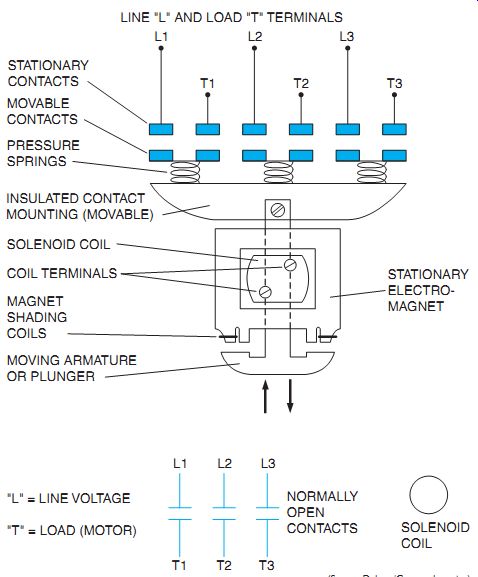
Ill. 1 Three-pole, solenoid-operated magnetic switch (contactor) and electrical
wiring symbols.
stationary contacts; movable contacts; pressure springs; insulated contact mounting (movable); solenoid coil; magnet shading coils; moving armature or plunger coil terminals
The operating principle that makes a magnetic starter different from a manual starter is the use of an electromagnet. Electrical control equipment makes extensive use of a device called a solenoid. This electromechanical device is used to operate motor starters, contactors, relays, and valves. By placing a coil of many turns of wire around a soft iron core, the magnetic flux set up by the energized coil tends to be concentrated; therefore, the magnetic field effect is strengthened. Because the iron core is the path of least resistance to the magnetic lines of force, magnetic attraction concentrates according to the shape of the magnetic core.
There are several different variations in design of the basic solenoid magnetic core and coil. Ill. 2 shows a few examples. As shown in the solenoid design of Ill. 2(C), linkage to the movable contacts assembly is obtained through a hole in the movable plunger.
The plunger is shown in the open de-energized position.
The center leg of each of the E-shaped mag net cores in Ill. 2(B) and (C) is made shorter than the outside legs to prevent the magnetic switch from accidentally staying closed (due to residual magnetism) when power is disconnected.
The major components of a three-phase contactor are shown in Ill. 3. The armature (moving part of the contactor) contains the movable load contacts. These contacts bridge across the stationary load contacts when the coil is energized. The core material is placed around the coil to provide a low-reluctance path for magnetic flux, creating a strong magnetic field.
When a magnetic motor starter coil is energized and the armature has sealed in, it's held tightly against the magnetic assembly. A small air gap is always deliberately placed in the center leg, iron circuit. When the coil is de energized, a small amount of magnetism remains.
If it were not for this gap in the iron circuit, the residual magnetism might be enough to hold the movable armature in the sealed-in position. This knowledge can be important to the electrician when troubleshooting a motor that won't stop.
The OFF or OPEN position is obtained by de energizing the coil and allowing the force of gravity or spring tension to release the plunger from the magnet body, thereby opening the electrical contacts. The actual contact surfaces of the plunger and core body are machine finished to ensure a high degree of flatness on the contact surfaces so that operation on alternating current is quieter. Improper alignment of the contacting surfaces and foreign matter between the surfaces may cause a noisy hum on alternating current magnets.
Another source of noise is due to loose laminations. The magnet body and plunger (armature) are made up of thin sheets of iron laminated and riveted together to reduce eddy currents and hysteresis, iron losses showing up as heat (see Ill. 4). Eddy currents are shorted currents induced in the metal by the transformer action of an AC coil. Although these currents are small, they heat up the metal, create an iron loss, and contribute to in efficiency. At one time, laminations in magnets were insulated from each other by a thin, non magnetic coating; however, it was found that the normal oxidation of the metallic laminations reduces the effects of eddy currents to a satisfactory degree, thus eliminating the need for a coating.
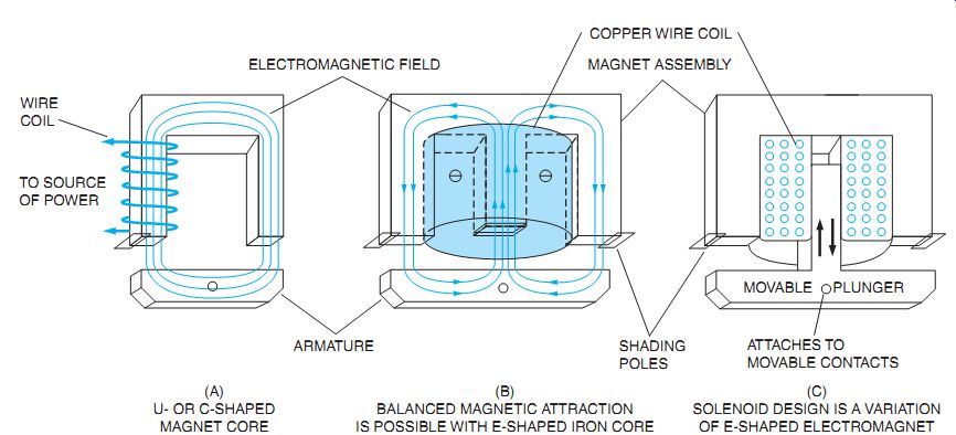
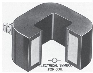
Ill. 2 Some variations of basic magnet core and coil configurations of
electromagnets.
(A) U- OR C-SHAPED MAGNET CORE; (B) BALANCED MAGNETIC ATTRACTION IS POSSIBLE WITH E-SHAPED IRON CORE; (C) SOLENOID DESIGN IS A VARIATION OF E-SHAPED ELECTROMAGNET
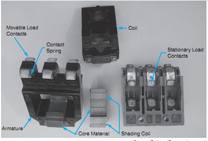
Ill. 3 The major working parts of a three-phase contactor.
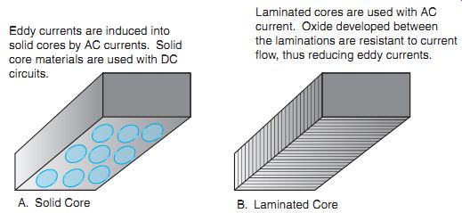
Ill. 4 Types of magnet cores. A. Solid Core Eddy currents are induced into solid
cores by AC currents. Solid core materials are used with DC circuits. B. Laminated
Core: Laminated cores are used with AC current. Oxide developed between the
laminations are resistant to current flow, thus reducing eddy currents.
SHADED POLE PRINCIPLE
The shaded pole principle is used to provide a time delay in the decay of flux in DC coils and to prevent chatter and wear in the moving parts of AC magnets. Ill. 5 shows a copper band or short-circuited coil (shading coil) of low resistance connected around a portion of a magnet pole piece. When the flux is increasing in the pole piece from left to right, the induced current in the shading coil is in a clockwise direction.
The magnetic flux produced by the shading coil opposes the direction of the flux of the main field. Therefore, with the shading coil in place, the flux density in the shaded portion of the magnet will be considerably less, and the flux density in the unshaded portion of the magnet will be more than if the shading coil were not in place.
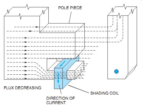
ill. 6 Pole face section; current is in the counterclockwise direction for
decreasing flux (conventional current flow).
Ill. 6 shows the magnet pole with the flux direction still from left to right, but now the flux is decreasing in value. The current in the coil is in a counterclockwise direction. As a result, the magnetic flux produced by the coil is in the same direction as the main field flux.
With the shading coil in place, the flux density in the shaded portion of the magnet will be larger and that in the unshaded portion will be less than if the shading coil were not used.
Thus, when the electric circuit of a coil is opened, the current decreases rapidly to zero, but the flux decreases much more slowly because of the action of the shading coil. This produces a more stable magnetic pull on the armature as the AC waveform alternates from maximum to minimum values and helps pre vent chatter and AC hum.
Use of the Shading Pole to Prevent Wear and Noise
The attraction of an electromagnet operating on alternating current is pulsating and equals zero twice during each cycle. The pull of the magnet on its armature also drops to zero twice during each cycle. As a result, the sealing surfaces of the magnet tend to separate each time the flux is zero and then contact again as the flux builds up in the opposite direction. This continual making and breaking of contact will result in a noisy starter and wear on the moving parts of the magnet. The noise and wear can be minimized in AC magnets by the use of shaded poles. As shown previously, by shading a pole tip, the flux in the shaded portion lags behind the flux in the unshaded portion. The diagram shows the flux variations with time in both the shaded and unshaded portions of the magnet.
The two flux waves are made as near 90 degrees apart as possible. Pull produced by each flux is also shown. If flux waves are exactly 90 degrees apart, the pulls will be 180 degrees apart and the resultant pull will be constant. However, with fluxes nearly 90 degrees apart, the resulting pull varies only a small amount from its average value and never goes through zero. Voltage induced in the shading coil causes flux to exist in the electromagnet, even when the main coil current instantaneously passes through a zero point. As a result, contact between the sealing surfaces of the magnet isn't broken and chattering and wear are prevented.
MAGNET COIL
Ill. 7 Magnet coil cutaway to show insulated copper wire wound on a spool
and protected by a molding.
The magnet coil has many turns of insulated copper wire that's tightly wound on a spool.
Most coils are protected by a tough epoxy molding that makes them very resistant to mechanical damage, Ill. 7.
Above-Normal Voltage Effects
The manufacturer makes available coils of practically any desired control voltage. Some starters are designed with dual-voltage coils.
NEMA standards require that the magnetic switch operates properly at varying control volt ages from a high of 110 percent to a low of 85 percent of the rated coil voltage. This range of required operation is then designed by the manufacturer. It ensures that the coil will withstand elevated temperatures at voltages up to 10 per cent over rated voltage and that the armature will pick up and seal in, even though the voltage may drop to 15 percent under the rating. Normally, power company service voltages are very reliable. Plant voltages may vary due to other loaded, operating machines and other reasons affecting the electrical distribution system.
If the voltage applied to the coil is too high, the coil will draw too much current. Excessive heat will be produced and may cause the coil insulation to break down and burn out. The magnetic pull will be too high and will cause the armature to slam in with too much force. The magnet pole faces will wear faster, leading to a shortened life for the controller. In addition, reduced contact life may result from excessive contact bounce.
Below-Normal Voltage Effects
Undervoltage produces low coil currents, thereby reducing the magnetic pull. On common starters the magnet may pick up (start to move) but not seal. The armature must seal against the pole faces of the magnet to operate satisfactorily. Without this condition, the coil current won't fall to the sealed value because the magnetic circuit's open, decreasing impedance (AC resistance). Because the coil isn't de signed to continuously carry a current greater than its sealed current, it will quickly get very hot and burn out. The armature will also chatter. In addition to the noise, there is excessive wear on the magnet pole faces. If the armature does not seal, the contacts may touch but not close with enough pressure, creating another problem. Excessive heat, with arcing and possible welding of the contacts, will occur as the controller attempts to carry a motor-starting current with insufficient contact pressure.
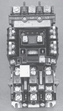
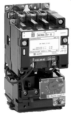
Ill. 8 Motor starter with overload relay.
POWER (OR MOTOR) CIRCUIT OF THE MAGNETIC STARTER
The number of poles refers to the number of power contacts determined by the electrical supply service. E.g., in a three-phase, three-wire system, a three-pole starter is required. The power circuit of a starter includes the main stationary and movable contacts and the thermal unit or heater unit of the overload relay assembly. This can be seen in Ill. 8 (and in Ill. 1, less the thermal overload relay assembly).
CONTACTS
Contact surfaces are generally a silver alloy for better electrical conductivity. Surfaces also have a mechanical "wiping" action from the point of contact to the sealing position when the starter is activated. This helps to keep the contacts clean. A good operating starter has no con tact bounce and has superior resistance to welding and arc erosion. Ill. 9 shows the 45-degree wedge action design of the contact.
MOTOR OVERHEAT
An electric motor does not know enough to quit when the load gets too much for it. It keeps going until it burns out. If a motor is subjected over a period of time to internal or external heat levels that are high enough to destroy the insulation on the motor windings, it will fail- burn out.
A solution to this problem might be to install a larger motor whose capacity is in excess of the normal horsepower required. This isn't very practical because there are other reasons for a motor to overheat besides excess loads. A motor will run cooler in snowy winter weather than in hot tropical summer weather. A high, surrounding air temperature (ambient temperature) has the same effect as higher-than-normal current flow through a motor-it tends to deteriorate the insulation on the motor windings.
High ambient temperature is also created by poor ventilation of the motor. Motors must get rid of their heat so any obstructions to this must be avoided. High inrush currents of excessive starting create heat within the motor. The same is true with starting heavy loads. There are several other related causes that generate heat within a motor such as voltage unbalance, low voltage, single phasing. In addition, when the rotating member of the motor won't turn (a condition called locked rotor), heat is generated.
It must be impossible to design a motor that will adjust itself for all the various changes in total heat that can occur. Some device is needed to protect a motor against expected overheating.
Ill. 9 45° wedge action design contacts.
Motor Overload Protection
Ill. 10 Three-phase motor starter with solid-state overload relay.
The ideal overload protection for a motor is an element with current sensing properties very similar to the heating curve of the motor.
This would act to open the motor circuit when full load is exceeded. The operation of the protective device is ideal if the motor is allowed to carry small, short, and harmless overloads but is quickly disconnected from the line when an overload has persisted too long. Dual-element, or time-delay, fuses may provide motor overload protection, but they have the disadvantage of being nonrenewable and must be replaced.
An overload relay is added to the magnetic switch that's shown in Ill. 1. Now it's called a motor starter. The overload relay assembly is the heart of motor protection.
A typical solid-state overload relay is shown in Ill. 10. The motor can do no more work than the overload relay permits. Like the dual-element fuse, the overload relay has characteristics permitting it to hold in during the motor accelerating period when the inrush current is drawn. Nevertheless, it still provides protection on small overloads above full-load current when the motor is running. Unlike the fuse, the overload relay can be reset. It can withstand repeated trip and reset cycles with out need of replacement. It is emphasized that the overload relay does not provide short-circuit protection. This is the function of overcurrent protective equipment like fuses and circuit breakers, generally located in the disconnecting switch enclosure.
Current draw by a motor is a convenient and accurate measure of the motor load. Motor heating is a combination of the amount of load and the ambient temperature. The overload relay employs some method of sensing motor current. The relay's ability to sense ambient temperature depends on the type of overload relay. Overload relays contain two separate sections; a current sensing section that's connected in series with the motor, and a contact section that contains a set of normally closed contacts connected in series with the coil of the motor starter, Ill. 11. The contacts of the overload relay are small and cannot carry the load current of a motor. For this reason the contacts are not connected in the motor circuit, but in the control circuit. In the case of a magnetic motor starter, if the motor should become overloaded, the normally closed contacts will open and de-energize the motor starter. The load contacts of the motor starter are utilized to disconnect the motor from the power line. In a manual starter, the overload relay trips a mechanical latch causing the load contacts to open and disconnect the motor from the power line.
To provide overload or running protection to keep a motor from overheating, overload relays are used on starters to limit the amount of cur rent drawn to a predetermined value. The NEC and local electrical codes determine the size of protective overload relays and heating elements, which are properly sized to the motor.
The controller is normally installed in the same room or area as the motor. This makes it subject to the same ambient temperature as the motor. The tripping characteristic of the proper thermal overload relay will then be affected by room temperature exactly as the motor is affected. This is done by selecting a thermal relay element (from a chart provided by the manufacturer) that trips at the danger temperature for the motor windings. When excessive current is drawn, the relay de-energizes the starter and stops the motor.
Overload relays can be classified as being either thermal, electronic, or magnetic. Magnetic overload relays react only to current excesses and are not affected by temperature. As the name implies, thermal overload relays depend on the rising ambient temperature and temperatures caused by the overload current to trip the overload mechanism.
Thermal overload relays can be further sub divided into two types-melting alloy and bimetallic.
Electronic or solid-state overload relays, Ill. 10, provide the combination of high speed trip, adjustability, and ease of installation.
They are ideal in many precise applications.
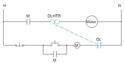
Ill. 11 An overload relay has a current sensing section that's connected
in series with the motor and a contact section that's connected in series
with the motor starter coil.
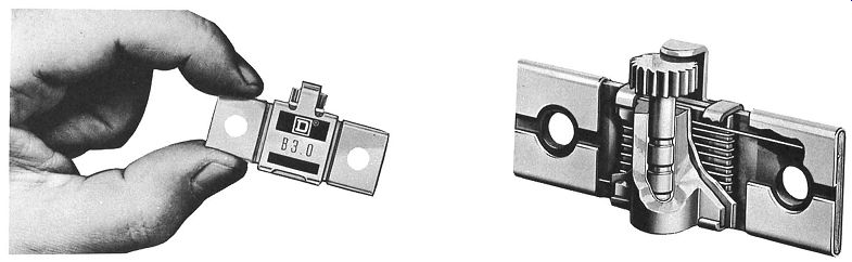
Ill. 12 Melting alloy type overload heater. Cutaway view (right) shows
construction of heater.
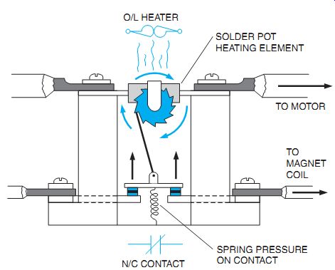
Ill. 13 Melting alloy thermal overload relay. A spring pushes the contact
open as heat melts, allowing the ratchet wheel to turn freely. Note the electrical
symbols for the overload heater and normally closed control contact.
Melting Alloy Thermal Units

Ill. 14 Typical overload heater chart.
Ill. 15 Solder melting type overload relay.
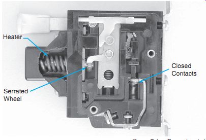
The melting alloy assembly consisting of a heater element and solder pot is shown in Ill. 12. The solder pot holds the ratchet wheel in one position. Excessive motor current passes through the heater element and melts an alloy solder pot. Because the ratchet wheel is then free to turn in the molten pool, it trips a set of normally closed contacts that's in the starter control circuit; this stops the motor, Ill. 13.
A cooling-off period is required to allow the solder pot to become solid again before the overload relay can be reset and motor service is restored.
Melting alloy thermal units are interchange able. They have a one-piece construction that ensures a constant relationship between the heater element and the solder pot. As a result, this unit can be factory calibrated to make it virtually tamperproof in the field. These important features are not possible with any other type of overload relay construction. To obtain appropriate tripping current for motors of different sizes, a wide selection of interchangeable thermal units (heaters) is available. They give exact overload protection to motors of different full load current ratings. Thermal units are rated in amperes and are selected on the basis of motor full-load current. For most accurate overload heater selection, the manufacturer publishes a number of rating tables keyed to the controller in which the overload relay is used. The units are easily mounted into the overload relay assembly and held in place with two screws.
Being in series with the motor circuit, the motor won't operate without these heating elements installed in the starter. A typical overload heater chart is shown in Ill. 14. A single phase solder melting type overload relay is shown in Ill. 15.
Bimetallic Overload Relays
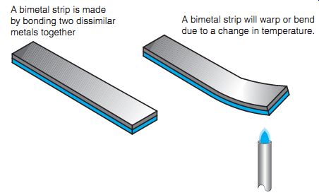
Ill. 16 A bimetal strip will bend or warp with a change of temperature.
A bimetal strip is made by bonding two dissimilar metals together.
A bimetal strip will warp or bend due to a change in temperature.
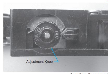
Ill. 17 Bimetal strip type overload relays permit the trip rating to be
adjusted.
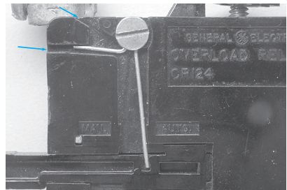
Ill. 18 The bimetal strip type overload relay can be set for manual or
automatic reset by changing the position of the spring.
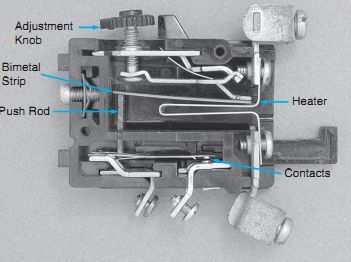
Ill. 19 Bimetal strip type overload relay.
Bimetal strip type overload relays operate on the principle that metals expand and contract with a change of temperature. A bimetal strip is made by bonding two dissimilar metals together, Ill. 16. Since the metals are dissimilar, they will expand and contract at different rates.
When the strip is exposed to a different temperature, it will warp or bend. Bimetal strip type overload relays have a couple of features that are different from the solder pot type. One difference is that the trip current can be adjusted by means of an adjustment knob, Ill. 17. A second difference is that most bimetal strip type over load relays can be set for automatic or manual reset. In the example shown in Ill. 18, a spring is moved between manual or automatic position.
In the automatic reset position, the relay contacts, after tripping, will automatically re close after the relay has cooled down. This is an advantage when the reset button is hard to reach. Automatic reset overload relays are not normally recommended when used with automatic (two-wire) pilot control devices. With this control arrangement, when the overload relay contacts reclose after an overload trip, the motor will restart. Unless the cause of the overload has been removed, the overload relay will trip again. This event will repeat. Soon the motor will burn out because of the accumulated heat from the repeated high inrush and the overload current. (An overload indicating light or alarm can be installed to catch attention before this happens.)
CAUTION: The more important point to consider is the possible danger to personnel. This unexpected restarting of the machine may find the operator or electrician in a hazardous situation as attempts are made to find out why this machine has stopped. The NEC® prohibits this later installation.
Most bimetallic relays can be adjusted to trip within a range of 85 to 115 percent of the nominal trip rating of the heater unit. This feature is useful when the recommended heater size may result in unnecessary tripping, while the next larger size won't give adequate protection.
Ambient temperatures affect thermally operated overload relays.
This ambient-compensated bimetallic over load relay is recommended for installations when the motor is located in a different ambient temperature from the motor starter. If the controller is located in a changing temperature, the overload relay can be adjusted to compensate for these temperature changes.
This thermal overload relay is always affected by the surrounding temperature. If a standard thermal overload relay were used, it wouldn't trip consistently at the same level of motor current whenever the controller temperature changed.
A bimetal strip type overload relay is shown in Ill. 19. The heater element is located closed to the bimetal strip. The temperature of the heater element is depends on the amount of motor current. If the heat becomes great enough, the bimetal strip will warp and cause a push-rod to open a set of normally closed contacts. After the relay has tripped, it's necessary to wait some period of time before the contacts can be re-closed. The cool down time is necessary to permit the bimetal strip to return to its normal position.
When it's necessary to provide overload protection for motors that draw large amounts of current, it's not practical to insert a large heater element in series with the motor leads.
Consider, for example, a motor that has a full load running current of 460 amperes. Overload relays are not designed to handle this amount of current. When overload protection must be provided for a large motor of this type, current transformers are used to reduce the motor cur rent to a lower value, Ill. 20. In this ex ample, three current transformers with a ratio of 600:5 are used to reduce the motor current.
These transformers are designed so that when 600 amperes of current flow through the primary winding, a current of 5 amperes will flow through the secondary winding in a shorted condition. The primary winding is the line sup plying power to the motor. The secondary winding is connected to the heater of an overload relay. A simple ratio can be used to determine the secondary current that should flow when 460 amperes of current flow to the motor.
600X _ 2300 (460 _ 5) X _ 3.833 amperes (2300 _ 600)
The overload heaters would be sized for a motor with a full-load current draw of 3.833 amperes.
A size 5 starter with current transformers is shown in Ill. 21. The transformers monitor the load current of each line and have a ratio of 300:5 amperes.
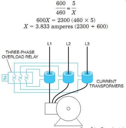
ill. 20 Current transformers are used to reduce the current to the overload
relay.
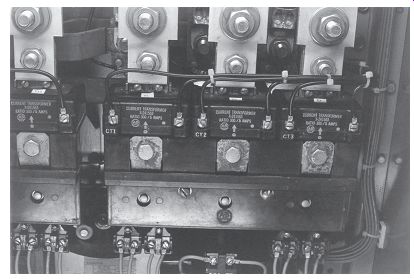
Ill. 21 Size 5 starter with current transformers that monitor the load
current of each line.
Magnetic Overload Relays
The magnetic overload relay coil is connected in series directly with the motor or is indirectly connected by current transformers (as in circuits with large motors). As a result, the coil of the magnetic relay must be wound with wire large enough in size to pass the motor current.
These overload relays operate by current intensity and not heat.
Magnetic overload relays are used when an electrical contact must be opened or closed as the actuating current rises to a certain value.
In some cases, the relay may also be used so that it's actuated when the current falls to a certain value. Magnetic overload relays are used to protect large motor windings against continued overcurrent. Typical applications are to stop a material conveyor when conveyors ahead become overloaded, and to limit torque reflected by the motor current.
All overload relays must allow some period of time before tripping to allow the motor to start.
Magnetic devices are very fast acting and can trip due to motor inrush current. Magnetic type overload relays employ a timing device called a dashpot permit the motor to start. A dashpot timer is basically a container, a piston, and a shaft, Ill. 22. The piston is placed inside the container and the container is filled with a special type of oil called dashpot oil. Dashpot oil maintains a constant viscosity over a wide range of temperatures. The type and viscosity of oil used are two of the factors that determine the amount of time delay for the timer. The other factor is setting the opening of the orifice holes in the piston, Ill. 23. Orifice holes permit the oil to flow through the piston as it rises through the oil. The opening of the orifice holes can be set by adjusting a sliding valve on the piston.
The dashpot overload relay contains a coil that's connected in series with the motor, Ill. 24. As current flows through the coil, a magnetic field is developed around the coil.
The strength of the magnetic field is proportional to the motor current. This magnetic field draws the shaft of the dashpot timer into the coil. The shaft's movement is retarded by the fact that the piston must displace the oil in the container. If the motor is operating normally, the motor current will drop to a safe level before the shaft is drawn far enough into the coil to open the normally closed contact, Ill. 25. If the motor is overloaded, however, the magnetic field will be strong enough to continue drawing the shaft into the coil until it opens the overload contact. When power is disconnected from the motor, the magnetic field collapses and the piston returns to the bottom of the container.
Check valves permit the piston to return to the bottom of the container almost immediately when motor current ceases.
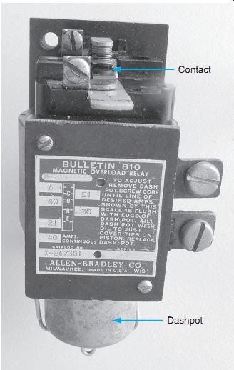
Dashpot overloads generally provide some method that permits the relay to be adjusted for different full load current values. To make this adjustment, the shaft, is connected to a threaded rod. This permits the shaft to be lengthened or shortened inside the coil. The greater the length of the shaft the less current required to draw the shaft into the coil far enough to open the contacts. A nameplate on the coil lists the different current settings for a particular overload relay. The adjustment is made by moving the shaft until the line on the shaft that represents the desired current is flush with the top of the dashpot container, Ill. 26. A dashpot overload relay is shown in Ill. 27.
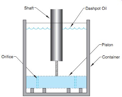
Ill. 22 Basic design of a dashpot timer.
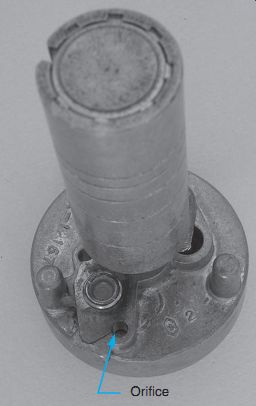
Ill. 23 The size of the orifice hole can be adjusted to change the time
setting of the dashpot timer.
Instantaneous Trip Current Relays
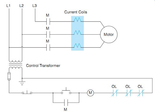
Ill. 24 The current coils of dashpot overload relays are connected in series
with the motor.
Ill. 25 Normally closed contact of a dashpot overload relay.
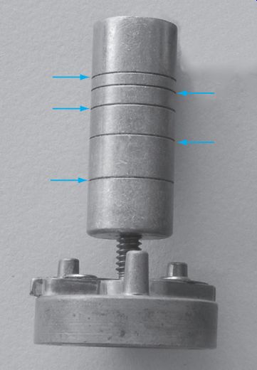
Ill. 26 Lines on the shaft are used to adjust the current setting.
Instantaneous trip current relays are used to take a motor off the line as soon as a predetermined load condition is reached. E.g., when a blockage of material on a woodworking machine causes a sudden high current, an instantaneous trip relay can cut off the motor quickly. After the cause of the blockage is re moved, the motor can be restarted immediately because the relay resets itself as soon as the overload is removed. This type of relay is also used on conveyors to stop the motor before mechanical breakage results from a blockage.
The instantaneous trip current relay does not have the inverse time characteristic. Thus, it must not be used in ordinary applications requiring an overload relay. The instantaneous trip current relay should be considered as a special-purpose relay.
The operating mechanism of the trip relay in Ill. 28 consists of a solenoid coil through which the motor current flows. There is a movable iron core within the coil. Mounted on top of the solenoid frame is a snap-action precision switch that has connections for either a normally open or a normally closed contact. The motor current exerts a magnetic pull upward on the iron core. Normally, however, the pull isn't sufficient to lift the core. If an overcurrent condition causes the core to be lifted, the snap action precision switch is operated to trip the control contact of the relay.
The tripping value of the relay can be set over a wide range of current ratings by moving the plunger core up and down on the threaded stem. As a result, the position of the core in the solenoid is changed. By lowering the core, the magnetic flux is weakened and a higher current is required to lift the core and trip the relay.
Number of Overload Relays Needed to Protect a Motor
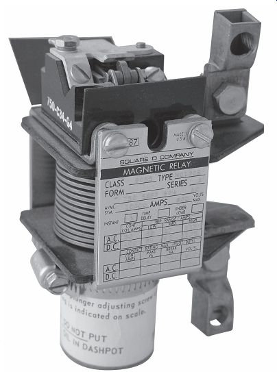
Ill. 27 Dashpot overload relay.
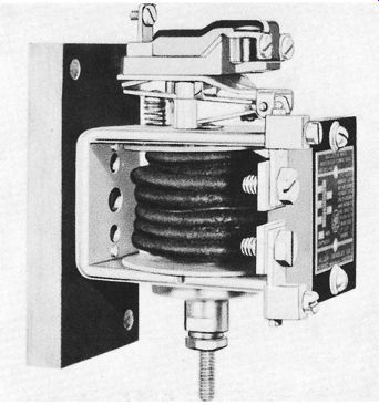
Ill. 28 Instantaneous trip current relay.
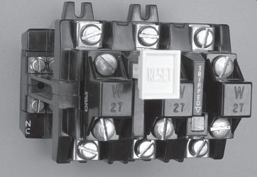
Ill. 29 A three-phase overload relay contains three separate heaters, but
only one set of contacts.
The NEC® requires that each phase of a motor be protected by an overload relay. There are two basic ways of protecting a three-phase motor.
Some starters use three separate single-phase overload relays. When this is done, the normally closed overload contacts are all connected in series so that any relay can open the circuit to the starter coil in the event of an overload. Other starters employ a three-phase overload relay, Ill. 29. A three-phase overload relay contains three heaters that are connected in series with the motor, but only one set of contacts. An overload on any phase will open the contacts and de-energize the motor starter.
A balanced supply voltage must be maintained for all polyphase load installations.
A single-phase load on a three-phase circuit can produce serious unbalanced motor cur rents. A large three-phase motor on the same feeder with a small three-phase motor may not be protected if a single-phase condition occurs, Ill. 30.
A defective line fuse, an open "leg" through a circuit breaker, a loose or broken wire anywhere in the conduit system or in a motor lead can result in single-phase operation. This will show up as a sluggish, hot-running motor. The motor won't start at all but will produce a distinct magnetic hum when it's energized. The three-phase motor may continue to operate (at reduced torque) when single phasing occurs. But once stopped, it won't restart. This is also a sign of a single-phase condition in a three-phase motor.
Unbalanced single-phase loads on three phase panel boards must be avoided. Problems may occur on distribution systems where one or more large motors may feed back power to smaller motors under open-phase conditions.
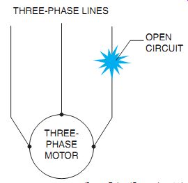
Ill. 30 A single-phase condition: two high currents, one zero current.
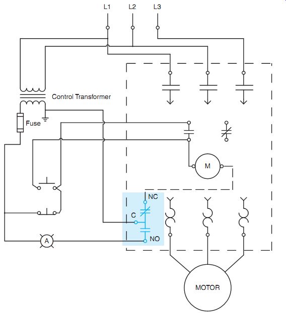
Ill. 31 Some overload relays contain a common terminal (C), a normally
closed contact terminal (NC), and a normally open contact terminal (NO).
OVERLOAD CONTACTS
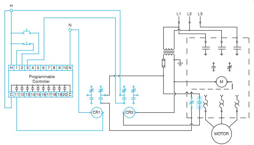
Ill. 32 Some overload relays contain both a normally closed and a normally
open contact. In this example the normally open contact is employed to signal
a programmable logic controller that the motor is tripped.
Although all overload relays contain a set of normally closed contacts, some manufacturers also add a set of normally open contacts as well.
These two sets of contacts are either in the form of a single-pole double-throw switch or as two separate contacts. The single-pole double-throw switch arrangement will contain a common terminal (C), a normally closed terminal (NC), and a normally open terminal (NO). There are several reasons for adding the normally open set of contacts. The starter shown if Ill. 31 uses the normally closed section to disconnect the motor starter in the event of an overload, and the normally open section to turn on a light to indicate that the overload has tripped.
Another common use for the normally open set of contacts on an overload relay is to provide an input signal to a programmable logic controller (PLC). If the overload trips, the normally closed set of contacts will open and disconnect the starter coil from the line. The normally open set of contacts will close and provide a signal to the input of the PLC, Ill. 32. Notice that two interposing relays, CR1 and CR2, are used to separate the programmable logic controller and the motor starter. This is often done for safety reasons. The control relays prevent more than one source of power from entering the starter or programmable controller. Note that the starter and programmable controller each have a separate power source. If the power were to be disconnected from the starter, for example, it could cause an injury if the power from the programmable controller were connected to any part of the starter.
AC MAGNETIC STARTERS
There are several manufacturers of magnetic motor starters, and most have a different appearance. Several starters are shown in Ill. 33.
The starter shown in Ill. 33(A) contains a three-phase overload relay. The reset handle is shown below the overload relay. The starter in Ill. 33(B) contains three separate single phase overload relays. The load contacts of each relay must be connected in series. Each overload relay contains a separate reset lever. The starter shown in Ill. 33(C) is part of a module de signed to plug into a motor control center (MCC).
The module contains a fused disconnect, control transformer, motor starter, and terminal strips for making connections. Note that the fused disconnect contains only two fuses. A jumper wire replaces the center fuse. This is common on delta connected three-phase systems with a B phase ground. The NEC does not require fuse protection for a grounded phase. The starter shown in Ill. 33(D) is the same as the starter shown in the module in photograph (C). Note the two normally open and two normally closed auxiliary contacts added to the sides of the starter. Many motor starters have the capability of adding additional auxiliary contacts to be used in the control circuit.
Starter Sizes
Magnetic starters are available in many sizes as shown in Table 1. Each size has been as signed a horsepower rating that applies when the motor used with the starter is operated for normal starting duty. All starter ratings comply with the NEMA Standards. The capacity of a starter is determined by the size of its contacts and the wire cross- sectional area. The size of the power contacts is reduced when the voltage is doubled because the current is halved for the same power (P _ 1 _ E). Power circuit contacts handle the motor load.
Three-pole starters are used with motors operating on three-phase, three-wire AC systems.
Two-pole starters are used for single-phase motors.
The number of poles refers to the power contacts, or the motor load contacts, and does not include control contacts for control circuit wiring.
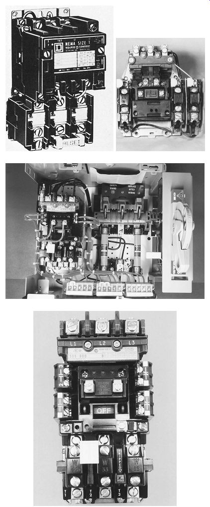
Ill. 33 Three-phase AC magnetic motor starters.
AC COMBINATION STARTERS
The circuit breakers and fuses of the motor feeders and branch circuits are normally selected for overcurrent, short-circuit, or ground fault protection.
With minor exceptions, the NEC and some local codes also require that every motor have a disconnect means. This means may be an attachment cord cap and receptacle, a nonfusible isolation disconnect safety switch, a fusible disconnect motor switch, or a combination starter.
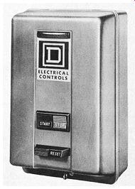
A combination starter (Ill. 34) consists of an across-the-line starter and a disconnect means wired together in a common enclosure.
Combination starters may have a blade-type disconnect switch, either fusible or nonfusible, or a thermal-magnetic trip circuit breaker. The starter may be controlled remotely with push buttons or selector switches, or these devices may be installed in the cover of the starter en closure. The combination starter takes little mounting space and makes compact electrical installation possible.
A combination starter provides safety for the operator because the cover of the enclosure is interlocked with the external, operating handle of the disconnecting means. The door cannot be opened while the disconnecting means is closed.
When the disconnecting means is open, all parts of the starter are accessible; however, the hazard is reduced because the readily accessible parts of the starter are not connected to the power line. This safety feature isn't available on separately enclosed starters. In addition, the starter enclosure is provided with a means for padlocking the disconnect in the OFF position.
Controller enclosures are available for every purpose and application.
Protective Enclosures
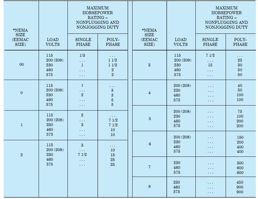
Tbl. 1 Standard Motor Starter Sizes and Ratings
The selection and installation of the correct enclosure can contribute to useful, safe service and freedom from trouble in operating electro magnetic control equipment.
An enclosure is the surrounding controller case, cabinet, or box. Generally, this electrical equipment is enclosed for one or more of the following reasons:
A. To shield and protect workers and other personnel from accidental contact with electrically live parts, thereby preventing electrocution.
B. To prevent other conducting equipment from coming into contact with live electrical parts, thereby preventing unnecessary electrical outages and indirectly protecting personnel from electrical contact.
C. To protect the electrical controller from harmful atmospheric or environmental conditions, such as the presence of dust or moisture, to prevent corrosion and interference of operation.
D. To contain the electrical arc of switching within the enclosure, to prevent explosions and fires that may occur with flammable gases or vapors within the area.
Ill. 34 Combination starter with circuit breaker, control transformer, control circuit fuse, and motor starter. The door cannot be opened unless the circuit breaker is open.
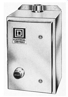
Ill. 35 General-purpose enclosure (NEMA 1).
You may readily understand why some form of enclosure is necessary and required. The most frequent requirement is usually met by a general-purpose, sheet steel cabinet. The conduit's installed with locknuts and bushings.
The presence of dust, moisture, or explosive gases often makes it necessary to use a special enclosure to protect the controller from corrosion or the surrounding equipment from possible explosions. Conduit access is through threaded openings, hubs, or flanges. In selecting and installing control apparatus, it's necessary to carefully consider the conditions under which the apparatus must operate. There are many applications where a general-purpose sheet steel enclosure does not give sufficient protection.
Watertight and dust-tight enclosures are used for the protection of control apparatus. Dirt, oil, or excessive moisture are destructive to insulation and frequently form current-carrying paths that lead to short circuits or grounded circuits.
Special enclosures for hazardous locations are used for the protection of life and property.
Explosive vapors or dusts exist in some departments of many industrial plants as well as in grain elevators, refineries, and chemical plants.
The NEC® and local codes describe hazardous locations. The Underwriters' Laboratories have defined the requirements for protective enclosures according to the hazardous conditions.
The NEMA has standardized enclosures from these requirements. Some examples are as follows.
General-Purpose Enclosures (NEMA 1)
These enclosures are constructed of sheet steel, and are designed primarily to pre vent accidental contact with live parts.
Covers have latches with provisions for padlocking, Ill. 35. Enclosures are intended for use indoors, in areas where unusual service conditions don't exist.
They do provide protection from light splash, dust, and falling debris such as dirt.
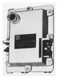
Watertight Enclosures (NEMA 4)
These enclosures are made of cast construction or of sheet metal of suitable rigidity and are designed to pass a hose test with no leakage of water. Watertight enclosures are suit able for outdoor applications on ship docks, in dairies, in breweries, and other locations where the apparatus is subjected to dripping or splashing liquids, Ill. 36.Enclosures that meet requirements for more than one NEMA type may be designated by a combination of type numbers, for example, Type 3-4, dusttight and watertight.
Dusttight Enclosures (NEMA 12)
These en closures are constructed of sheet steel and are provided with cover gaskets to exclude dust, lint, dirt, fibers, and filings. Dust-tight enclosures are suitable for use in steel and knitting mills, coke plants, and similar locations where nonhazardous dusts are present. Mounting is by means of outside flanges or mounting feet.
Hazardous Locations (NEMA 7) Class 1 enclosures are designed for use in hazardous locations where atmospheres containing gasoline, petroleum, naphtha, alcohol, ace tone, or lacquer solvent vapors are present or may be encountered. Enclosures are heavy, gray iron castings, machined to pro vide a metal-to-metal seal, Ill. 37.
Table 2 assists in the proper selection of motor control enclosures. You may note that many enclosures are overlapping in their protection abilities.
NOTE: Applicable and enforced national, state, or local electrical codes and ordinances should be consulted to determine the safe way to make any installation.
Ill. 36 Watertight enclosure (NEMA 4).
Ill. 37 Hazardous location enclosure (NEMA 7)
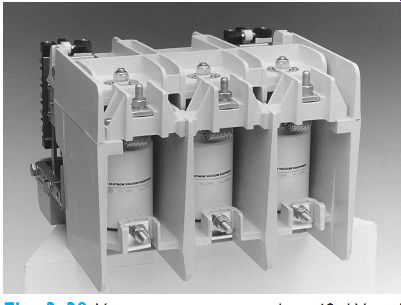
Ill. 38 Vacuum contactor rated at 12 kV and 400 amperes.
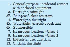
Table 2 Motor Controller Enclosure Selection
1. General-purpose, incidental contact with enclosed equipment.
3. Dusttight, raintight
3R. Rainproof, sleet resistant
4. Watertight, dusttight
4X. Watertight, corrosive resistant
6P. Submersible
7. Hazardous locations-Class 1
9. Hazardous locations-Class 2
12. Industrial use, dusttight
13. Oiltight, dusttight
VACUUM CONTACTORS
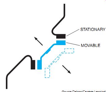
Vacuum contactors enclose their load contacts in a sealed vacuum chamber. A metal bellows connected to the movable contact permits it to move without breaking a seal, Ill. 38.
Sealing contacts inside a vacuum chamber permits them to switch higher voltages with a relatively narrow space between the contacts without establishing an arc. The contactor shown in Ill. 38 is rated 12 kV and 400 amperes.
An electric arc is established when the volt age is high enough to ionize the air molecules between stationary and movable contacts.
Medium-voltage contactors are generally large because they must provide enough distance between the contacts to break the arc path. Some medium-voltage contactors use arc suppressors, arc shields, and oil immersion to quench or prevent an arc. Vacuum contactors operate on the principle that if there is no air surrounding the contact, there is no ionization path for the establishment of an arc. Vacuum contactors are generally much smaller in size than other types of medium-voltage contactors.
NEMA AND IEC
NEMA is an acronym for National Electrical Manufacturers Association. Likewise, IEC is an acronym for International Electrotechnical Commission. The IEC establishes standards and ratings for different types of equipment just as NEMA does. The IEC, however, is more widely used throughout Europe than in the United States. Many equipment manufacturers are now beginning to specify IEC standards for their products in the United States also. The main reason is that much of the equipment produced in the United States is also marketed in Europe. Many European companies won't purchase equipment that isn't designed with IEC standard equipment.
Although the IEC uses some of the same ratings as NEMA-rated equipment, there is often a vast difference in the physical characteristics of the two. Two sets of load contacts are shown in Ill. 39. The load contacts on the left are used in a NEMA-rated 00 motor starter, whereas the ones on the right are used in an IEC-rated 00 motor starter. Notice that the surface area of the NEMA-rated contacts is much larger than the IEC-rated contacts. This permits the NEMA rated starter to control a much higher current than the IEC starter. In fact, the IEC-rated 00 starter contacts are smaller than the contacts of a small eight-pin control relay, Ill. 40.
Due to the size difference in contacts between NEMA- and IEC-rated starters, many engineers and designers of control systems specify a one to two larger size for IEC-rated equipment than would be necessary for NEMA-rated equipment. A table showing the ratings for IEC starters is shown in Ill. 41.
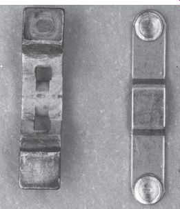
Ill. 39 The load contacts on the left are from a NEMA-rated 00 motor starter.
The load contacts on the right are from an IEC-rated 00 motor starter.
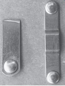
Ill. 40 The control contact of an eight-pin control relay is shown on the
left. The load contacts of an IEC rated 00 starter are shown on the right.
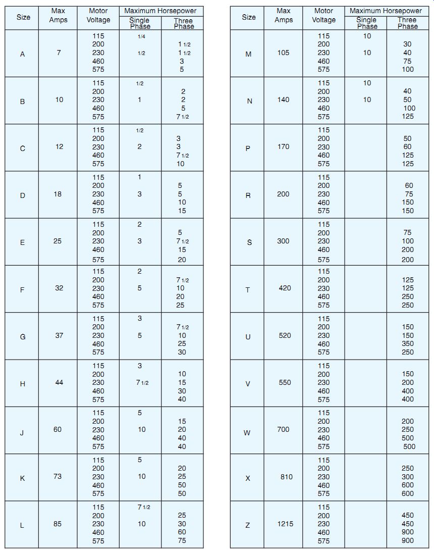
Ill. 41 IEC motor starters rated by size, horsepower, and voltage for 60-Hz
circuits.
QUIZ
When answering questions related to troubleshooting, you may want to refer to "Motor Startup and Troubleshooting Basics."
1. What is a magnetic line voltage motor starter?
2. How many poles are required on motor starters for the following motors:
(a) 240-volt, single-phase induction motor, (b) 440-volt, three-phase induction motor?
3. If a motor starter is installed according to directions but won't start, what is a common cause for the failure to start?
4. Using the time limit overload or the dashpot overload relay, how are the following achieved: time-delay characteristics; tripping current adjustments?
5. What causes the AC hum or chatter in AC electromagnetic devices?
6. What is the phase relationship between the flux in the main pole of a magnet and the flux in the shaded portion of the pole?
7. In what AC and DC devices is the principle of the shaded pole used?
8. What does the electrician look for to remedy the following conditions:
a. loud or noisy hum?
b. chatter?
9. What type of protective enclosure is most commonly used and what is its NEMA number?
10. What advantage is there in using combination starters?
11. What safety feature does the combination starter provide that individual motor starting assemblies don't?
12. List the probable causes if the armature does not release after the magnetic starter is de-energized.
13. How is the size of the overload heaters selected for a particular installation?
14. What type of motor starter enclosure (include NEMA number and class) is recommended for an installation requiring safe electrical operation around an outside, inflammable paint-filling pump? Select the best answer for each of the following.
15. The magnetic starter is held closed
a. mechanically
b. by 15 percent undervoltage
c. by 15 percent overvoltage
d. electrical magnetically
16. When a motor starter coil is de-energized,
a. the contacts stay closed
b. it's held closed mechanically
c. gravity and spring tension open contacts
d. it must cool for a restart
17. An AC magnet may hum excessively due to
a. improper alignment
b. foreign matter between contact surfaces
c. loose laminations
d. all of these
18. AC magnets are made of laminated iron
a. for better induction
b. to reduce heating effect
c. for AC and DC use
d. to prevent chattering
19. The purpose of overload protection on a motor is to protect the
a. motor from sustained overcurrents
b. wire from high currents
c. motor from sustained overvoltage
d. motor from short circuits
20. The number of magnetic starter poles refers to
a. the number of power, motor, or load contacts
b. the number of control contacts
c. the number of north and south poles
d. all of these
21. Motors may burn out because of
a. overloads
b. high ambient temperatures
c. poor ventilation
d. all of the above
22. The purpose of a shading coil on an AC electromagnetic pole tip is to
a. prevent overheating of the coil
b. limit the tripping current
c. limit the closing current
d. prevent chattering
23. The current drawn by a motor is
a. low on starting
b. an accurate measurement of motor load
c. an inaccurate measurement of motor load
d. none of these
24. Thermal overload relays react to
a. high ambient temperatures and excessive heating due to overload currents
b. heavy mechanical loads
c. heavy electrical loads
d. rising starting currents
25. The thermal relay heating element is selected
a. 15 percent under voltage
b. 10 percent over voltage
c. from the motor's FLA and a manufacturer's selection chart
d. by ambient temperature
26. When the reset button does not reestablish the control circuit after an overload, the probable cause is
a. the overload heater is too small
b. the overload trip has not cooled sufficiently
c. the auxiliary contacts are defective
d. the overload heater is burned out
27. If an operator pushes a start button on a three-phase induction motor and the motor starts to hum, but not run, the probable trouble is
a. one fuse is blown and the motor is single phasing
b. the overload trip needs resetting
c. the auxiliary contact is shorted
d. one phase is grounded
28. A combination starter provides
a. disconnecting means
b. overload protection
c. short-circuit protection
d. all of these
29. Vacuum contactors
a. are quieter in operation than standard contactors
b. can control higher voltages in a smaller space
c. are more economical to purchase than conventional contactors
d. require the connection of a vacuum pump when in operation
30. What does IEC stand for?
a. Intensity of current, EMF, and Capacitance
b. Internal Electrical Connection
c. International European Committee
d. International Electrotechnical Commission