AMAZON multi-meters discounts AMAZON oscilloscope discounts
Linear power supplies have been popular since the beginning of vacuum-tube electronics. Their operation is simple, but their efficiency is quite poor in the range of 30% to 40%. Fig. 1 shows the electrical schematic for a typical linear power supply. From this diagram note that the first part of the power supply is exactly like the rectifier sections presented earlier. The power supply uses a transformer and a four-diode full-wave bridge rectifier to produce the pulsing dc output waveforms. A capacitor is used as a filter to smooth out the dc. The remainder of the circuit contains a regulator and the load. The regulator is the part of the circuit that makes a linear power supply different from the newer switch-mode power supplies.
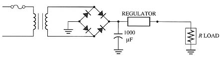
Above: Fig. 1: Schematic of a linear power supply.
The regulator in this circuit acts as a voltage divider between the regulator and the load. To understand this operation, think of the load as a fixed resistance and the regulator as a variable resistance. When two resistances are connected in series, such as the regulator and the load resistance, the amount of voltage supplied to them will be shared. The amount of voltage will be split by the ratio of the resistance. For example, if the ratio of the resistance is 2:1, the regulator will have twice as much voltage measured across it than the load. If the power supply delivered 30 volts, the regulator would have 20 volts dropped across it, and the load would have 10 volts measured across it.
If the resistance of the regulator was changed so that the ratio of resistance with the load was 1:1, the voltage across the regulator would drop to 15 volts, and the voltage measured across the load terminals would be increased to 15 volts. This means that the voltage to the load terminals will change anytime the resistance in the regulator changes. This type of circuit is simple to operate, which makes the linear power supply easy to manufacture and troubleshoot. The problem with this type of power supply is all of the voltage that is dropped across the regulator is wasted energy. If the regulator drops 10% of the voltage and the load gets 90%, the power supply is operating somewhat efficiently. If the regulator drops 90% and the load gets 10%, one can notice that this is a tremendous amount of wasted energy. The other drawback of the linear power supply is that since it must drop a portion of the supply voltage through the regulator, the components in the regulator must be sized large enough to handle the excess heat that is generated. This tends to make the linear power supply up to two times larger (and heavier) than the new switch-mode power supplies.