AMAZON multi-meters discounts AMAZON oscilloscope discounts
Another circuit that provides a full-wave output uses four diodes and a regular transformer without the center tap. This circuit uses two diodes at a time to rectify each half of the sine wave. Fig. 1 shows an example of this type of circuit. The input sine wave and the output full wave (two half-cycles) are also shown. Notice that ac voltage from the bottom terminal of the transformer is applied to the bridge where the cathode of diode 1 and the anode of diode 4 are connected, and from the top terminal of the transformer where the cathode of diode 2 and the anode of diode 3 are connected. This means that the ac voltage is connected where the anode of one diode is connected to the cathode of the second diode.
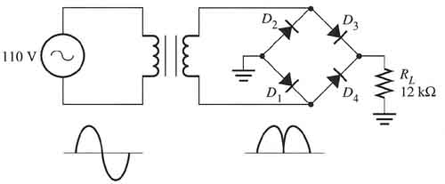
Above: Fig. 1 The electrical diagram of a four-diode full-wave bridge rectifier.
The output for the bridge circuit will have its positive dc voltage terminal at the point where the cathode of diode 3 and diode 4 are connected, and the negative point of the circuit will be where the anode of diode 1 and diode 2 are connected. This point is also grounded.
When ac voltage is applied to the four-diode full-wave bridge rectifier, the positive half of the sine wave will be rectified by diodes 1 and 3. The negative half of the sine wave is rectified by diodes 2 and 4. From the top circuit in Fig. 2 notice that the positive half-cycle of the ac is shaded, and the first half-wave is shaded to indicate the output for this part of the circuit. The bottom circuit shows the negative half of the sine wave being rectified. The path the electrons would travel through the bridge is also shown. Notice that electron flow is always against the arrows of the diodes.
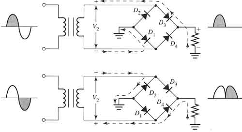
Above: Fig. 2 Electronic schematic that shows the current path of the positive and negative half-cycles of the sine wave as it's rectified through the bridge.
In some industrial power supplies the four-diode full-wave bridge rectifier is drawn slightly differently, even though it operates exactly like the previous circuit. Fig. 3 shows an example of the full-wave bridge drawn with the diode bridge turned on its side so they look like a square rather than a diamond. The bridge is illustrated this way because the six-diode three-phase bridge rectifier uses a similar pattern.
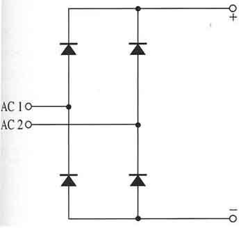
Above: Fig. 3 Electronic schematic of the four-diode bridge where the diodes are shown in a box formation rather than a diamond. The circuit function is exactly like the bridge shown in Fig. 2.
One can also begin to notice the four-diode full-wave bridge uses two diodes at a time to rectify each half-cycle of the ac sine wave. If one diode of either of the two diode sets is faulty, an open will occur for that half-cycle and the output voltage of the bridge will drop approximately in half. If one diode from each set develops an open, the output from the bridge will be zero.
The equations for calculating the dc average voltage at the output of the four-diode bridge are similar to the two-diode full-wave bridge except the equations for the four-diode bridge must account for a 0.7 volt drop in each of the two diodes used to rectify the positive and negative half-cycles. The equation to determine the Vdc av must be calculated in two steps. The first step will use an equation to determine the peak voltage (less the 1.4 volt drop for the two diodes):
VP =(V secondary rms x 1.414) - 1.4 V
The second equation is:
Vdc av = 2VP/π
Exercise
Calculate the V dc av for a four-diode full-wave rectifier that is connected to the secondary of a transformer that provides 120 volts ac rms. (Remember to include the 1.4 volt drop through the diodes.)
Solution
From the equation
Vp =(V sec rms x 1.414) - 1.4 V
Vp=(120x1.414)-1.4V
Vp = 168.28 V
From the equation
Vdc av = 2 VP/π
Vdc av = 2 308.28 VP/π
Vdc av = 98.12 V

