AMAZON multi-meters discounts AMAZON oscilloscope discounts
4 SWITCHES
An electric switch is a device that opens and closes to control some load in an electric circuit. Electric switches can be opened and closed by temperature, pressure, humidity, flow, or by some manual means. You must become familiar with the symbols used for switches because in most cases they control the loads in the system. The symbol will also indicate what is initiating the action of the switch.
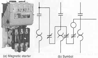
ill. 20 (a) Magnetic starter ( Furnas Electric Company)
(b) …and its symbol
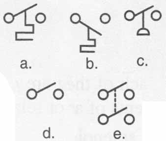
A manually operated switch is a switch that's opened and closed by manual force. ill. 21 shows a simple manually operated switch. The poles of a manual switch are the number of contacts that are included in the switch. The throw indicates how the switch may be operated. E.g., a single-pole—single-throw switch has one set of contacts and two positions: an open and a closed position, as shown in ill. 21. A double- pole—double-throw switch has two sets of contacts and three positions, as shown in ill. 22. Symbols for these two switches and for two other basic types of manual switches are shown in ill. 23.
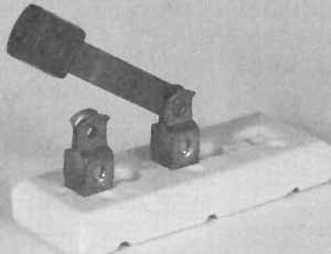 ill. 21 Single-pole—single-throw manual switch
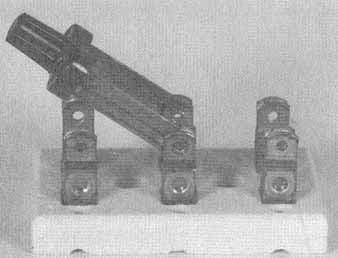 ill. 22 Double-pole—single-throw manual switch
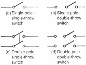 ill. 23 Symbols for manual switches: (a) Single-pole— single-throw
switch; (b) Single-pole-double-throw switch; (c) Double-pole-single-throw
switch; (d) Double-pole-double-throw switch
ill. 23 Symbols for manual switches: (a) Single-pole— single-throw
switch; (b) Single-pole-double-throw switch; (c) Double-pole-single-throw
switch; (d) Double-pole-double-throw switch
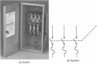 ill. 24 Three-pole fusible disconnect: (b) Symbol; (a) Switch
There are other types of manual switches used in the industry. The disconnect switch is used to open and close the main power source to a piece of equipment or load. ill. 24 shows a three-pole disconnect switch and its symbol. The push-button switch, as shown in ill. 25, is a switch used to open and close a set of contacts by pressing a button. The symbols for the normally closed and the normally open push-button switches are also shown in ill. 2
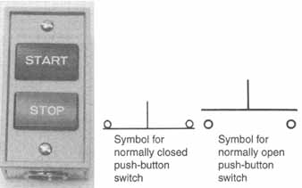 ill. 25 Push-button switch: Symbol for normally closed push-button
switch; Symbol for normally open push-button switch
ill. 25 Push-button switch: Symbol for normally closed push-button
switch; Symbol for normally open push-button switch
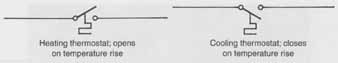 Fig 26 Symbols for heating and cooling thermostats: Heating thermostat;
opens on temperature rise; Cooling thermostat; closes on temperature
rise
Fig 26 Symbols for heating and cooling thermostats: Heating thermostat;
opens on temperature rise; Cooling thermostat; closes on temperature
rise
The most important type of switch in a control system is the mechanically operated switch. Thermostats are mechanically operated switches used in most control systems. Thermostats are said to be mechanically operated because the temperature-sensing element moves a set of contacts by a mechanical linkage. Thermostats are designed for heating, cooling, or both. The cooling thermostat is designed to close on a temperature rise and open on a temperature fall. The heating thermostat is designed to open on a temperature rise and close on a temperature fall. The symbols for these two types of thermostats, shown in ill. 26, indicate their function. ill. 27 shows a modern thermostat.
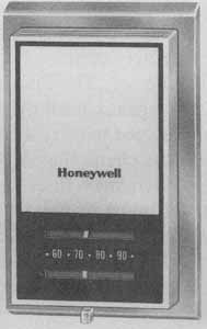 ill. 27 Thermostat ( Honeywell, Inc.)
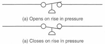 ill. 28 Symbols for pressure switches: (a) Opens on rise in pressure; (a) Closes on rise in pressure
Pressure switches are used for different functions in modern control circuits. The purpose of the pressure switch determines whether it opens or closes on a rise or fall in pressure. The pressure range of the switch isn't part of the symbolic representation. ill. 28 shows the symbols for pressure switches. Letter designations in the symbols often denote the pressure ranges and purposes of the switches. ill. 29 shows some common pressure switches used in the industry.
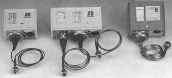
ill. 29 Some common pressure switches
5 SAFETY DEVICES
Safety devices are important in today’s modem systems. Components are becoming more expensive each year. Thus, it's vital that these components be protected from adverse conditions such as low voltage, high ampere draw, and overheating. It is for this reason that you should become familiar with symbols for safety devices. Overloads and safety devices are some times a combination of a load and a switch. They differ from the relay in their purpose and overall design.
All motors are designed to operate on a certain current draw. If for some reason this rating is exceeded, the motor must be cut off immediately to prevent damage and possible destruction of the component. A burned-out motor is often caused by a malfunction in the safety devices.
The fuse is the simplest type of overload device. The fuse is effective against a large overload, but it's less effective against small overloads. The fuse isn'thing more than a piece of metal designed to carry a certain load. Any higher load will cause the fuse to break the circuit. ill. 30 shows two symbols for a fuse. ill. 31 shows some common fuses in use today.
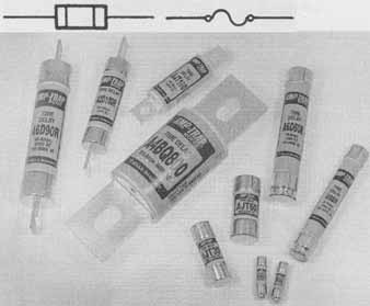
ill. 30 Symbols for fuses;
ill. 31 Some common fuses
The second type of overload device is designed to protect the motor against small and large overloads. This type is divided into two categories: thermal and magnetic. The thermal overload is operated by heat, and the magnetic overload is operated by magnetism, which is directly proportional to the current draw.
The thermal overload can be a pilot duty device, which breaks the control circuit and locks the motor out. The pilot duty types of overloads are most common on motors larger than 3 horsepower. The thermal overload can also be a line voltage device, which breaks the power line to the component being protected.
The bimetal element is the simplest of the thermal overloads. When it gets warm, it warps to open the circuit, as shown symbolically in ill. 32. Some bimetal elements are furnished with heaters, as shown symbolically in ill. 33. The heater allows the bimetal disc to react to an overload more quickly because the current flow is proportional to heat.
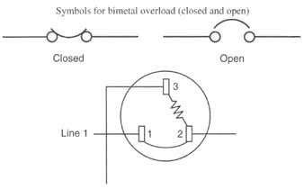
ill. 32 Symbols for bimetal overload (closed and open); ill.
33 Symbol for three-wire bimetal overload
The thermal overload relay, whose symbol is shown in ill. 34, is a simple device with a thermal element and a switch that opens on a rise in temperature.
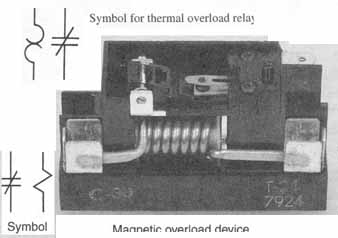
ill. 34 Symbol for thermal overload relay; ill. 35 Magnetic overload
device
The magnetic overload symbol is the same as the symbol for a relay with one normally closed contact. The current flow is relayed to the overload coil. Since current flow is proportional to the strength of the magnetic field, the relay can be designed to energize only on a high current draw. ill. 35 shows a magnetic overload and its symbol. The letter designation of this device will distinguish between the magnetic overload and the common relay.
6 TRANSFORMERS
The transformer decreases or increases the incoming voltage to a desired voltage. In most air-conditioning control circuits, it's not practical to pull large wires for a long distance. Therefore, a 24-volt control circuit, which is safer, less expensive, and a better method of control, is used. ill. 36 shows a transformer and its symbol. The voltage is also given with the symbol in some cases.
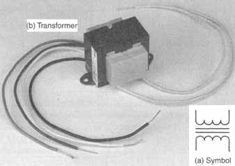
ill. 36 Transformer: (a) Symbol; (b) Transformer
7 SCHEMATIC DIAGRAMS
Most modern heating, cooling, and refrigeration systems are becoming more complex with more controls and safety devices. Advances in controls and control systems require you to be able to read schematic diagrams. If you are able to read schematic diagrams, you will know what the unit should be doing.
The schematic diagram is the most useful and easiest to follow of any electric diagram. The schematic diagram tells how, when, and why a sys tem works as it does. In most cases, service technicians use schematic diagrams to troubleshoot control systems. The schematic wiring diagram includes the symbols and the line representations so the user can easily identify loads and switches along with the circuits.
All electric circuits contain a source of electrons, a device that uses electron flow, and a path for the electrons to follow. In most cases, the source of electrons is an alternating current voltage supply. The device using the electron flow is a motor, heater, relay coil, or any other load device. The path for the electrons to follow is a wire or any type of conductor.
In the schematic diagram, the source of electrons, the power supply, is represented by two lines drawn downward and listed as L1 and L2, as shown in ill. 37. There is a potential difference of 240 volts between L1 and L2. If a path is created between Li and L2, current will flow.
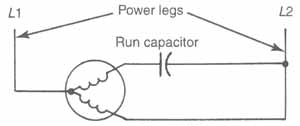
ill. 37 Schematic diagram showing power supply
All electrical loads in the unit are placed between L1 and L2, along with the switches controlling the load. ill. 38 shows a complete circuit in schematic form with a compressor and the switch (thermostat) that controls it. When the switch is closed, the compressor will run. In ill. 38, the source of electrons is from L1 and L2, the path is the connecting wire, and the device using the electron flow is the compressor. The compressor operates when the thermostat is closed.
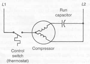
ill. 38 Schematic diagram of a complete circuit: Control switch
(thermostat); Compressor; run capacitor
ill. 39 shows a full schematic diagram similar to the diagrams you will be using on the job. All schematic diagrams are broken down into a circuit-by-circuit arrangement. Most schematic diagrams contain a legend that cross-references the components and their letter designation to the name of the component. Look at the legend in ill. 39.
Legend:
|
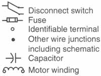
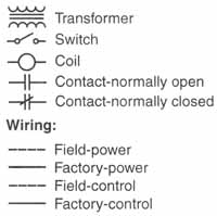
Symbols: Wiring:
|
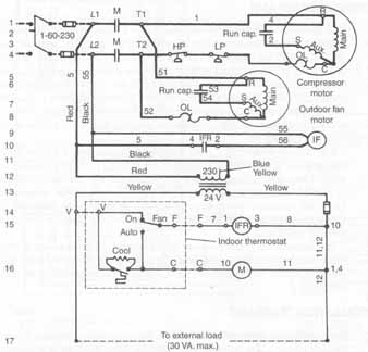
ill. 39 Complete schematic diagram for small packaged unit ( Westinghouse Electric Corp.)
8 PICTORIAL DIAGRAMS
The pictorial diagram, also referred to as a label or line diagram, is intended to show the actual internal wiring of the unit. The pictorial diagram shows all the components of the control panel as a blueprint, including all the interconnecting wiring. It does not show the unit to scale, however. Components that are not shown in the control panel itself are shown outside the panel and labeled. The pictorial diagram is used to locate specific components or wires when troubleshooting from a schematic diagram. A typical pictorial diagram used in the industry is shown in ill. 40.
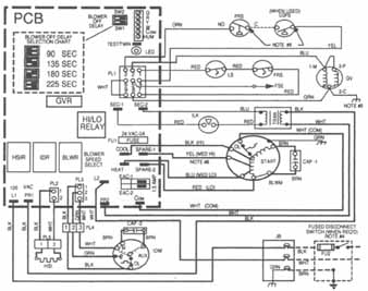
ill. 40 A typical pictorial diagram used in the industry ( Carrier Corporation, Syracuse, NY)
 |
|
It is difficult to determine from a pictorial diagram how a system operates, and only an experienced mechanic can follow a complex pictorial diagram. Thus, most air-conditioning technicians use the schematic diagram to find the cause of the problem. Then they use the pictorial diagram to locate the position of the component at fault. In cases where the wiring is simple, however, a pictorial diagram may be the only diagram furnished with the equipment.
The factual diagram consists of a pictorial diagram along with a schematic diagram. Many air-conditioner manufacturers supply factual diagrams so service technicians can locate the relay or component in the control panel.
9 INSTALLATION DIAGRAMS
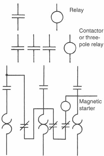
The installation diagram is used to help the installation electrician to wire the unit properly. The diagram gives specific information about terminals, wire sizes, color coding, and breaker or fuse sizes. The diagram does not provide details about equipment operation because the electrician has no need for this information. ill. 41 shows an installation diagram. The installation wiring diagram shows little internal wiring and is therefore almost useless to industry technicians.
SUMMARY
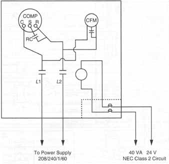
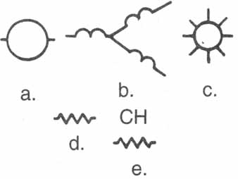
Loads are devices that use electricity to do useful work. ill. 42 gives a review of the symbols used for solenoids, motors, and heaters, the typical loads found in the industry. Most symbols have some type of letter designation to identify more clearly the component referred to.
ill. 41 A typical installation diagram: To Power Supply 208/240/1/60;
40VA 24V NEC Class 2 Circuit
ill. 54.2 Review of symbols for loads: Motor, Solenoid, Heater
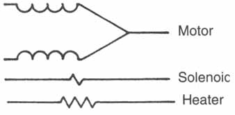
ill. 43 Review of symbols used for contactors and relays: Relay; Contactor
or three pole relay; Magnetic starter
Loads are controlled by relays and contactors, which share the same symbol and perform similar tasks. The major difference between relays and contactors is the amount of current each can carry. If a compressor is being operated by a device, you can assume the device is a contactor. If a small fan motor is being operated by a device, you can assume the device is a relay. A relay is used for small loads, and a contactor is used for large loads. ill. 43 reviews the symbols for some of these devices.
Relays and contactors are controlled by switches. Some of the switches used in the industry are manual, push-button, thermostat, and pressure. Thermostats are made for two purposes: to operate either a heating or a cooling system. The symbols for thermostats denote whether they are used for heating or cooling. Pressure switches are much the same as thermostats; their symbols also denote which way they open or close and under what condition. Pressure switches can be used for low or high pressure and are usually denoted by letter designations.
In any system using motors, protective devices are important to prevent damage to the motors or to larger components of the system. The most important type of safety device is for motor protection. A fuse, magnetic overload, thermal overload line break, thermal overload pilot duty, or a thermal overload relay could be used. Many overloads are built directly into the larger components.
Transformers are devices that increase or decrease the incoming voltage to some desired voltage. Transformers are used in the industry mainly in control circuits.
Schematic diagrams tell air-conditioning, heating, or refrigeration technicians when and why a system works as it does. Schematic diagrams show the symbols for devices and the interconnecting wiring of a unit in a circuit- by-circuit arrangement. Schematic diagrams are used most frequently by service technicians to troubleshoot equipment and systems.
Pictorial diagrams show an exact layout of the control panel with the external components shown outside the panel and labeled. The pictorial diagram can be used as a troubleshooting diagram on a simple system, such as a window air conditioner. In most cases, pictorial diagrams are used to find the placement of a component in the panel. Factual diagrams are a combination of the schematic and pictorial, with each shown separately.
Installation diagrams are used to help the installation electrician correctly connect the wiring to the unit. See the dedicated section of this guide for most of the electrical symbols used by major refrigeration, heating, and air-conditioning manufacturers.
REVIEW QUESTIONS
1. What are the three types of electrical diagrams used in the heating, cooling, and refrigeration industry?
2. A load is an electrical device that:
a. produces electricity
b. directs the flow of electricity
c. assists in the starting of motors
d. uses electricity to do useful work
3. What is the major load of an air-conditioning system?
4. Identify the following symbols for loads:
What is the major difference between a contactor and a relay?
6. What do the terms “normally open” and “normally closed” refer to with regard to a switch or set of contacts? Draw a normally open and normally closed contact.
7. What is the difference between a magnetic starter and a contactor?
8. Identify the following symbols for relays and contactors:
9. Draw a heating and a cooling thermostat and explain the difference between them.
10. A three-pole contactor would allow how many paths for current flow?
11. A disconnect switch is used to _____
a. open and close the main power source to a piece of equipment
b. stop and start a compressor
c. control the operation of an electric heater
d. open when an unsafe condition occurs
12. What determines whether a pressure switch opens or closes on a rise of pressure?
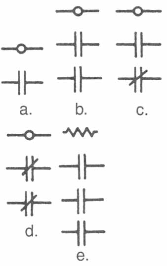
13. Identify the following symbols for switches:
14. What is the difference between a thermal overload and a magnetic overload? Draw the symbol for each.
15. What is the purpose of a transformer? Draw the symbols for a transformer.
16. Which of the following isn't a requirement for an electric circuit?
a. a source
b. a path
c. a load
d. a signal light
17. What is the purpose of a legend on a schematic diagram?
18. A factual diagram is ___
a. a pictorial diagram with wire colors denoted
b. a combination of pictorial and installation wiring diagrams
c. a combination of schematic and pictorial wiring diagrams
d. none of the above
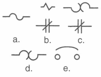
19. Identify the following symbols for safety devices.
20. Which of the following are not components of a contactor or relay?
a. a solenoid
b. contacts
c. thermal element
d. mechanical linkage
21. True or False: The schematic diagram tells service technicians how to wire a system.
22. What is the difference between a pilot duty and a line break overload?
23. What type of switch would be used to open or close set of contacts at a certain pressure?
24. What is the purpose of a fuse in an electrical system?
25. True or False: A solenoid valve is a device that opens or closes to control the flow of some element in the system.
26. What is a signal light used for in a control system?
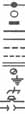
27. Change the following normally open elements from the de-energized position to the energized position.
-||-
28. Draw the symbols for the following electrical devices.
a. heating thermostat
b. pressure switch (closes on rise)
c. heater
d. motor
e. solenoid coil
f. normally open push-button switch
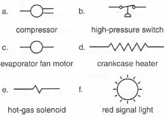
29. Add letter designations to the symbols to indicate the following:
a. compressor —O=
b. high-pressure switch
c. evaporator fan motor —O—
d. crankcase heater —/\/\/\—
e hot-gas solenoid —\/\—
f. red signal light
30. Draw a symbol for a magnetic starter.