AMAZON multi-meters discounts AMAZON oscilloscope discounts
OBJECTIVES:
• Explain what electrical loads are and their general purpose in heating, cooling, and refrigeration systems.
• Give examples of common loads used in heating, cooling, and refrigeration systems.
• Identify the symbols of common loads used in heating, cooling, and refrigeration systems.
• Explain the purpose of relays and contactors in heating, cooling, and refrigeration systems.
• Identify the symbols of relays and contactors in heating, cooling, and refrigeration systems.
• Explain the purpose of switches and the types used in heating, cooling, and refrigeration systems.
• Identify the symbols of switches in heating, cooling, and refrigeration systems.
• Identify the symbols and purpose of other miscellaneous controls in heating, cooling, and refrigeration systems.
• Identify the different types of wiring diagrams used in the industry and the purpose of each.
KEY TERMS:
- Contactor
- De-energized
- Disconnect switch
- Energized
- Factual diagram
- Fuse
- Heater
- Installation diagram
- Load
- Magnetic overload
- Magnetic starter
- Motor
- Normally
- Normally closed
- Normally open
- Pictorial diagram
- Pilot duty device
- Pole
- Pressure switch
- Push-button switch
- Relay
- Schematic diagram
- Signal light
- Solenoid
- Switch
- Thermal overload
- Thermostat
- Throw
- Transformer
INTRODUCTION
Because of the complexity of today’s air-conditioning, heating, and refrigeration systems, industry technicians should be able to read and interpret all kinds of wiring diagrams. Electric wiring diagrams contain a wealth of information about the electrical installation and operation of the equipment. The installation mechanic depends on the wiring diagram for the correct installation of the wiring to the unit. The technician uses the electrical diagrams as a guide in troubleshooting the electric system of a unit. It would be impossible for wiring diagrams to be composed of photographs of various components of the equipment. They would be too large and in many cases too complex due to the number of wires that are carried to certain devices. Thus, symbols are used in wiring diagrams to represent such system components as compressors, indoor fan motors, thermostats, pres sure switches, and heaters. Industry technicians must be able to identify most symbols and know where to look up the remainder. Most manufacturers use similar symbols for each type of electric component, although there are some minor differences in symbols between some major manufacturers. Thus, knowledge of the basic symbols is essential if you are to be successful in the industry.
We begin our study with a discussion of the various types of electric loads found in the industry and the basic symbol used for each device.
1 LOADS
Loads are electric devices that consume electricity to do useful work. Loads are devices such as motors (ill. 1), solenoids (ill. 2), resistance heaters (ill. 3), and other current-consuming devices. The sizes of loads vary from devices with a small current draw, such as a light bulb, a small fan motor, and solenoids, to large motors that could use upward of 100 amperes.
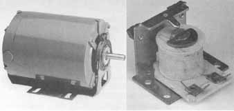
(left) Electric motor; (right) A solenoid used
to operate a contactor
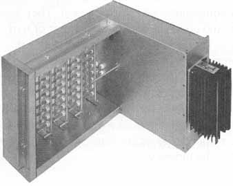
A resistance heater ( Indeeco, St
Louis, MO)
Loads are the most important part of a heating, cooling, or refrigeration system because they do all the work in the system. Loads operate compressors, which compress and transfer refrigerant in a system. They operate fans, which move air. They operate the solenoid part of a relay, which starts and stops loads. Also, loads operate with other devices that perform useful work. Industry technicians should be able to recognize the common symbols for loads and know where to look up the symbols for little-used loads, because each electric wiring diagram is composed of symbols and their interconnecting wires.
In the following paragraphs, we will take a close look at several different kinds of loads used in the industry.
Motors
A motor is an electric device that consumes electric energy to rotate a device in an electric system. Motors are used in the industry to rotate devices such as compressors (ill. 4), condenser fan motors (ill. 5), pumps (ill. 6), and other devices that require rotating movement. Motors are the largest and most important loads in heating, cooling, and refrigeration systems.
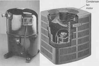
Compressor ( Copeland, Sidney, OH); A condenser fan motor on a residential air- conditioning condensing
unit ( American Standard Air Conditioning)
The symbols shown in ill. 7 are the most common symbols used to represent motors.
A letter designation tells you what purpose the motor serves in the sys tem. ill. 8 shows several symbolic representations of different uses of motors. Careful attention should be given to symbols representing motors because in some cases, a motor has an internal overload, as shown in ill. 8(e).
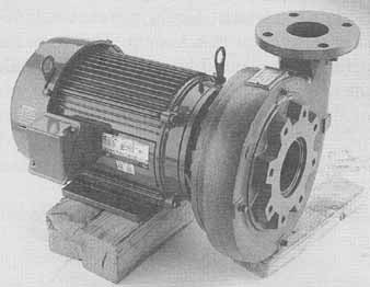
ill. 6 A centrifugal pump ( Peerless Pump Co., Indianapolis,
IN)
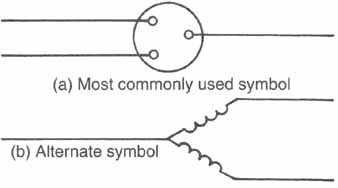
ill. 7 Symbols for an electric motor
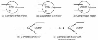
ill. 8 Symbols representing some common uses of motors: (a) Condenser
fan motor, (b) Evaporator fan motor, (c) Compressor motor, (d) Compressor
motor, (e) Compressor motor with internal overload.
Solenoids
The solenoid is a device that creates a magnetic field when energized and causes some action to an electric component such as a relay or valve. A common solenoid used to operate a relay is shown in ill. 9. The solenoid is considered a load because it consumes electricity to do useful work. Solenoids are devices that control some element in a system. Solenoid valves are valves that open and close, stopping or starting a flow. Solenoid coils used in relays and contactors will be discussed later in this section. Some common solenoid valves are hot-gas solenoids, reversing-valve solenoids, and liquid-line solenoids. ill. 10(a) shows a solenoid valve and a solenoid coil, and ill. 10(b) shows its symbol.
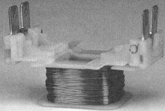
ill. 9 Solenoid coil used to operate relay
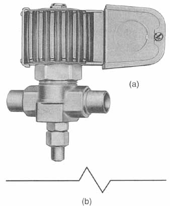
ill. 10 (a) Solenoid valve with coil ( Sporlan) (b) Symbol Heaters
Heaters are loads that are found in many systems and wiring diagrams. A heater takes electric energy and converts it to heat. In some cases, electric resistance heaters are used to heat homes. Heaters might also be used to heat a small object or area. The symbol for all heaters is the same. Only a letter designation tells you specifically why the heater is used. ill. 11 shows the symbols used for heaters, along with some common letter designations.
Signal Lights
A signal light is a light that's illuminated to denote a certain condition in a system. The letter inside the signal light symbol denotes the color of the signal light, as shown in ill. 12. Signal lights come in a variety of colors and are not limited to the colors shown in ill. 12. A signal light is used to show that a piece of equipment is operating or that it's operating in an unsafe condition. Signal lights are usually energized when a piece of equipment or component is started.

ill. 11 Symbols for commonly used electric heaters: (a) Heater,
(b) Crankcase heater, (c) Supplementary heater

ill. 12 Symbols for signal lights showing the color of the light: (a),
Red, (b) Green, (c) Blue
2 CONTACTORS and RELAYS
Contactors and relays are devices that open and close a set or sets of electric contacts by the action of a solenoid coil. The contactor or relay is com posed of a solenoid and the contacts. A relay is shown in ill. 13. A contactor is shown in ill. 14. When the solenoid is energized, the contacts will open or close, depending on their original position (that is. if they were open, they will close, and vice versa).
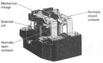
Relay ( Siemens Electromechanical
Components, Inc.): Mechanical linkage; Solenoid coil; Normally-open contacts;
Normally closed contacts
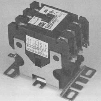
Contactor
In an air-conditioning control system, we must have some method of con trolling loads. In most cases, a relay or contactor is used. Relays and contactors are widely used in control systems. Thus, it's essential that industry technicians be able to identify the symbols for relays and contactors.
The main difference between a relay and contactor is the size of the device. A contactor is simply a large relay. Usually, the devices are distinguished by their rated current flow. A contactor can carry 20 amperes or more. A relay is designed to carry less than 20 amperes. Contactors are commonly used where the ampere draw of a device is more than 20 amperes. A relay would rarely be used to carry over 20 amperes.
Contactors and relays play an important part in the control system of any air conditioner, refrigerator, or heater. E.g., contactors and relays are used to stop and start different loads in a refrigeration system. Compressors, in most air-conditioning systems, are controlled by a contactor or magnetic starter. Relays can be used for pilot duty, that's , for con trolling another relay or contactor. The most important fact to remember is that most control systems have many relays and at least one contactor. These relays or contactors always control some load.
Relays and contactors are composed of three parts: the contact and the coil, or solenoid, and the mechanical linkage. The contact makes the electrical connections. ill. 15 shows the symbol for a pole, or contact, of a relay or contactor. The term “pole” refers to one set of contacts. However, in some cases the relay or contact might have two or three poles, which means two or three sets of contacts. The coil or solenoid, the second part of the relay, is energized (voltage is supplied) and , through a magnetic field, closes the contact or contacts. Either symbol shown in ill. 17 can be used to represent a relay or contactor coil. The symbol for the relay or contactor is the same if each has the same number of poles and if their purpose is basically the same, with the exception of the ampere rating of the device.
All symbols are usually shown in the de-energized position. This means that there is no electric potential to the coil of the device. ill. 15 shows a “normally open” contact in the de-energized position.

ill. 15 Symbol for a normally open pole of a relay. ill. 16 (bottom)
Symbol for a normally closed pole of a relay or contactor.
![]()
ill. 17 Symbols for relay or contactor coil; either symbol may be
used for each device.
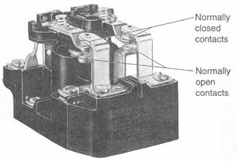 ill. 18 Normally closed and open set of contacts ( Siemens
Electromechanical Components, Inc.)
The term normally refers to the position of a set of contacts when the device is de-energized. ill. 15 shows a normally open set of contacts and ill. 16 shows a normally closed set of contacts. Normally open contacts close and normally closed contacts open when the relay or contactor is energized. In ill. 18, a relay is shown with normally open and closed contacts.
The terms “normally open,” “normally closed,” “energized,” and “de energized” are important in understanding relays and contactors on wiring diagrams. ill. 19(a) shows a relay with two normally open contacts and one normally closed contact in the de-energized position (with no volt age to the coil). ill. 19(b) shows the same contacts in the energized position (with voltage to the coil). In the de-energized position, the current won't flow through contacts 1 and 2, but current will flow through con tact 3. In the energized position, the current flow is through 1 and 2 but not through 3.

ill. 19 Symbols showing de-energized and energized relays
3 MAGNETIC STARTERS
A magnetic starter is the same type of device as a contactor in terms of the ampere rating of the device. But the magnetic starter has a means of overload protection in it, whereas the contactor has none. ill. 20 shows a picture of the magnetic starter and its symbol. The principle of operation of the magnetic starter will be covered in an upcoming section.