AMAZON multi-meters discounts AMAZON oscilloscope discounts
Once upon a time, getting at the circuitry of a consumer product was a piece of cake. Remove a few screws, pop off the back, and there it was. Providing access to the inner workings was a tradition begun in the vacuum tube days, when the unit's owner needed to get inside on a frequent basis to change tubes, lamps and fuses.
After semiconductor technology replaced the troublesome tubes with considerably more reliable transistors, there was still the expectation that the buyer might have a legitimate need to reach the circuit board. Early solid-state products even put the transistors in sockets! As semiconductors got sturdier, the sockets went away, which was good since their flaky connections caused more failures than did the transistors themselves. There were still lamps and fuses to contend with, though, and access was expected and easy.
That was before today's age of complex, ultra-miniaturized circuits, complete lack of user-serviceable parts (mostly thanks to the LEDs that replaced lamps), and lawsuits. These days, no manufacturer wants you anywhere near the stuff under the hood.
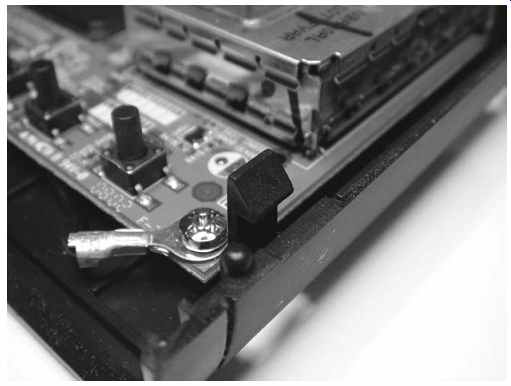
FIG. 1 Hidden plastic snap
Consequently, many equipment cases are deliberately sealed, or at least made pretty tough to open. Most AC adapters are ultrasonically welded together and have to be cracked open; even the expensive ones are considered non-repairable items by their makers. Lots of laptop computers, video projectors, MP3 players and TVs sport hidden snaps, so they won't pop apart even after you remove the screws. See FIG. 1. And anyone who's ever tried to take apart a certain American computer company's sleekly designed products knows the meaning of frustration; they're clamped together seamlessly and tightly in a clearly deliberate attempt to keep you out.
So how do you open up these crazy things? Sometimes, others have suffered before you and have posted step-by-step disassembly instructions on their Web sites, with clear photos of the whole process. If you can't fathom how to get something apart, it pays to do a Web search on "disassemble __," with the blank filled in by the name or model number of your product. Some companies selling parts post these helpful tutorials, facilitating your getting to the point of having a reason to order their wares.
If you can't find disassembly instructions, you'll have to wing it. With or without help, this is the stage at which you have the most opportunity to wreck your device! Without X-ray vision, you can't know if that tiny screwdriver you're using to pry the case halves apart or unhook the hidden snaps you're not even sure are there might be ripping a tiny component off the circuit board or causing some other drastic damage.
You also have no idea whether a ribbon cable may join the two halves and be torn when they suddenly separate. And nothing is more frustrating than thinking you're about to repair something and destroying it instead, before you ever get a chance to look for the original problem.
Despite all this gloom and doom, you can get into nearly any product successfully and safely if you're careful and take your time. Disassembly is not a trivial process; expect it to take a significant portion of the total repair time, at least with the smallest, most complex devices. There are some tricks to the endeavor, and we're going to explore them now. But first, some rules:
Rule number one • Always disconnect power before taking something apart.
This is true with battery-operated products as well as AC-powered ones. Even if there's no danger to you, you have a much higher chance of damaging the device if power is connected when things come apart, whether the unit is turned on or not. Pull the plug, yank the batteries.
Rule number two • Remove everything you can before going for the screws.
Battery covers, recording media (tapes, discs, memory cards), rubber covers over jacks, lanyards-if it comes off, take it off. There's no need to pull knobs from a front panel if you don't anticipate having to remove the panel, but that's about it.
Everything else should go. And don't be too surprised if you later wind up having to take off those knobs after all.
Rule number three • Never force anything. If the case won't come apart, or some corner seems stuck, there's a reason. Perhaps snaps are hiding on the inside of the plastic. Screws are sometimes hidden under labels and rubber feet. Run your fingernail over labels, looking for the indentation where a screw head might be lurking. If you find one, peel back the label just enough to get to the hole. Peel back the rubber foot near the stubborn area; just because the other feet aren't hiding screws doesn't mean this one isn't. You'll probably have to glue the foot back on later, but it's a necessary consequence of peeling the original adhesive.
Rule number four • Don't let frustration drive you to make a destructive mistake. Even the calmest tech can get riled up when a recalcitrant patient tries his or her patience badly enough. The most common errors are to start moving too fast, to force something, or, in extreme cases, to smack the casing, hoping it'll loosen up. Bad idea! Okay, I admit it: I once threw a really nice, rather expensive pocket stereo cassette player against the wall after a maddening, futile hour of trying to take it apart, but I don't recommend the exercise. It felt good, but, needless to say, that repair job was over before it began. Plus, for weeks I was stepping on pieces of that poor little thing I'd murdered. I couldn't help but think of Poe's The Tell-Tale Heart every time something went crunch underfoot. At least it was my own player, and not something I'd have to replace for a customer or lose a job over.
Separating Snaps
Popping apart hidden snaps is almost an art form in itself. First, be absolutely sure you've removed all the necessary screws. Take a look at the bottom of the unit to see if there might be slots into which you can put a screwdriver to pop the snaps. Those are common on AC-operated devices whose bottoms face shelving, but not on pocket toys.
If you do find slots, shine a flashlight into one and see if you can deduce what needs to be pressed in which direction to unhook the snap. Pop one open while pulling the case halves apart with your free hand. To prevent accidental reinsertion, keep holding them apart while you do the next snap on that side of the case. Once you have a couple of snaps open, you won't need to continue the forced separation, and the rest should open easily.
If you find no slots, pick one side of the case and press on the seam around the edge, looking for inward bending of the plastic. Move slowly and feel for slight movements indicating where hidden snaps may lie. When the plastic gives a little, press harder and attempt to pull the seam up. If it won't budge despite your best efforts, move to another part of the case and try again. After you get one snap undone, the rest will release a lot easier.
If no amount of effort will release the snaps, you might be tempted to slip a small screwdriver into the seam and pry it open. It's a last-ditch procedure, but it usually works. It's almost certain to break snaps, though, and cause some visible damage on the outside of the case.
Even with the best technique, you'll break a few while you get the hang of it, and occasionally even after you're an expert. Luckily, it's not the end of the world. Often the loss of a snap or two has little or no effect on a product's integrity, but sometimes the reassembled case can feel loose or have a gap along the desnappified seam. Just save the broken pieces in case you need to melt them back on later.
Removing Ribbons
Ribbon cables have replaced wires in small products. They offer much higher density with a lot less mess, and we couldn't have today's complex pocket devices without them. The ribbons are delicate, though, and removing them from their sockets requires care.
Some ribbon connectors have latches that press the ribbon's bare conductor fingers against the socket's pins. Others have no latches and rely on the thickness of the ribbon to make a firm connection. Either style may have a stiff reinforcement tab at the end of the ribbon, but the latchless style always does.
Before pulling out a ribbon, take a Sharpie marker and put a mark on both the ribbon and the socket so you'll know how to orient the cable during reassembly. Use a Sharpie; other markers may rub off. If other nearby ribbons are similar enough that you could possibly confuse which goes where, use a unique mark on each one.
Now examine the socket closely. If you see small tabs at either end, it has a latch.
Even without tabs, it might have a flip-up latch. Pulling a ribbon from a latch-type connector without opening the latch first can easily tear the ribbon. You don't want that! Ribbon cables are custom made for each product, and you aren't going to find a replacement unless you can dig up a dead unit for parts. A torn ribbon usually means a ruined device.
If there is no latch, grasp the ribbon at the reinforced tab and pull steadily. Don't jerk or you'll almost certainly destroy it. Pull gently at first and then harder if the ribbon doesn't move. With some of the larger cables, you might be surprised at how much force it takes to get them out of their sockets. If you need to pull hard, hold the socket down on the board with your other hand to prevent ripping it from its solder joints. It's rare for a ribbon to need that kind of force, but I've seen it a few times.
Whatever you do, don't pull on the unreinforced part of the ribbon; it won't withstand the stress.
If there's a latch, open it first. There are two basic styles: slide and flip-up. Slide latches have little tabs at the ends of the socket. A fingernail or the end of a flat-blade screwdriver will pull them open. It's best to open them at the same time, to keep the sliding part from getting crooked or breaking off, but gently opening them one at a time usually works fine.
Flip-up latches open easily with a fingernail. You can use a screwdriver, but be careful not to scrape and damage the ribbon cable. Especially with a very small connector, open the flip-up slowly and carefully, as they break quite easily. It helps to pull them from near their ends, lifting both ends at the same time, rather than from the middle. If you break one, keeping enough pressure on the ribbon to make a proper connection with the socket is next to impossible.
Pulling Wire Connectors
Larger items may have a mixture of ribbon cables and good old wire assemblies.
Circuit board-mounted connectors for wiring rarely have latches. If they do, the latch will be large and obvious, something you squeeze with your thumb while pulling on the connector. Most wire connectors simply pull straight up. Reorientation is not an issue with these, but marking is still advisable if other nearby connectors could cause confusion. We've all been taught through the years never to pull on the wires when removing plugs, but that's what you have to do with these because the plug fits entirely into the socket, leaving nothing else to grab. Grasp the wires, pull steadily without jerking, and the connector should pop out.
Before you do, though, be certain there actually is a connector! Groups of wires sometimes terminate in what look like connectors, but the wires go right through the plastic and are soldered directly to the board. Obviously, you don't want to pull on those.
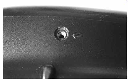
FIG. 2 Arrow indicating screw removal
Layers and Photos
Remember those little cups I suggested you collect, way back in Section 2? Here's where you will use them. Unlike the simpler products of yesteryear, modern gadgetry is often built in layers. Perhaps the topmost layer is a display. Under that lies a metal shield. Beneath that is a circuit board, and there's another board under that one as well. Behind all of it is the battery compartment and a little board for connectors.
Ribbon connectors join the layers, with several on each side of the main boards, and you can't get to the lower layers without removing the upper ones first. Sounds like a huge product, doesn't it? Perhaps a home theater receiver or a laptop computer? Hah! I just described a typical digital camera! Just wait till you try to get to the back of the mechanism in a pocket-sized MiniDV camcorder.
To reach the innermost spaces, the layers have to be stripped away in precisely the reverse order of their original assembly. And, naturally, the problem you're chasing is at the bottom layer, right? Each layer is held by screws, and they're probably different sizes from those holding the next layer down. Some may even be different from others in the same layer. Not all screws always have to be removed; some only grip small internal parts, and unscrewing them may drop a nut or a washer deep into the works. Especially in devices with motors or speakers, both of which use strong magnets, a lost metal part can get pulled in and cause real trouble later. Some companies stamp a little arrow by the screws that must come out, especially on the outside of the product's case, but that's not an industry standard. See FIG. 2. If you do see the arrows, remove only the screws that have them. If there are no arrows, start with the screws near corners, and see if that frees up the case. No? Then you'll have to remove them all and hope for the best.
As you unscrew a screw, observe how it comes out. It should rise, indicating that it's screwed into a fixed object, not a nut. If it seems very loose as soon as you start to turn it counterclockwise, screw it back in again and see if it tightens down without slippage. If not, then there probably is a nut on the other side, and you don't want to unscrew it! Nuts are almost never used on the screws holding case halves together.
How would the manufacturer tighten such a screw without having access to the nut? Once in a great while, you do find a nut or a little metal bracket on the inside, glued into a plastic shelf so it'll stay put after the case is assembled. It's rare, though, and found mostly on older gear.
When you remove screws, take a good look at each one after it's out. Pay careful attention to the length, comparing it to the last one. Very often, otherwise identical looking screws are of different lengths, and putting one that's too long in the wrong hole when you reassemble the device can make it poke into something, causing a short or other serious damage.
As you take out screws from a layer, put them in one of those cups. If different lengths are used, make a quick drawing of which went where on a little piece of scrap paper or a sticky note, and put that in the cup too. Now put another cup into the first one, covering the contents of the lower cup. When you start on the next layer, put its screws into the open cup, and so on. If the device is especially complicated or has many layers, take a photo of each layer, with the stack of cups visible in the picture.
That way, you'll know which set of screws goes with which layer-just count the number of cups in the photo. You might be surprised at how easy it is to lose track of that after the unit has sat in pieces on your bench for days or weeks. When the disassembly operation is complete, you'll have a stack of cups, with the screws from the last layer in the top cup. Place an empty cup in the top one to keep the screws securely inside, and put the stack somewhere safe and out of your way.
Opening a Shut Case
Let's take a look at some case opening procedures for common products, starting with the easiest and working up to the really challenging adventures.
Receivers and Amplifiers
Most shelf-style audio gear opens up with no hassle. You'll find four screws, two on each side, two or three smaller ones at the top edge of the back panel, and perhaps one to three on top, just rear of the front panel. Unscrew them all, put them in a cup, and the top should slide off. Often, you'll have to spread the sides slightly while lifting the back edge, as the front edge is under the top of the front panel.
VCRs, CD and DVD Players
Most VCRs open the same way, but there are some variations. Some have screws on the bottom instead of the sides. You won't find one on top behind the front panel, but you may find some on the back's upper edge. On many VCRs, you have to slide the top straight back before trying to lift the rear edge.
CD and DVD players require much the same thing, but the front edge may have a lip fitting into a groove on the front panel.
TVs and LCD Monitors
Today's flat-panel TVs and monitors usually unscrew from the back. The panels are recessed from the bezel around them, so you should be able to lay the set face down gently on your bench, after sweeping the table's surface and checking for anything that could stick up and put pressure on the LCD or plasma screen. You may find lots of screws of various lengths. Be very careful to note which go where, because under those screws is the back of the display panel! You really don't want to mix up the lengths and screw anything into that when you put it back together.
Older CRT-type TVs have screws at the top and bottom of the back. They may be recessed, requiring a long screwdriver. It's best to lay small sets face down on a pillow before removing the screws. Some larger units let you remove the back without upsetting the stability of the TV, but many require that you tilt them forward a little bit to get the back off. That can be disastrous if the set flops onto its face. If you can put the TV on the floor and tilt it against a wall only a few degrees, that's your safest option.
Just remember that the neck of the picture tube, which will be in your face when you pull off the back, is dangerous, both electrically and mechanically. Be extra-careful not to hit the tube's neck, and don't touch the circuit board at the back. Nasty voltages live there, and they can persist even after the set has been turned off and unplugged.
Turntables
Turntables are an old technology, but they enjoy a following among audiophiles, so there are plenty of them still around. Also, turntables are uniquely shaped and somewhat delicate, making them awkward to service.
A turntable's platter may be driven by a rubber wheel, a belt or a direct-drive motor turning at the same rate as the record. Most better turntables are belt- or direct driven. To change the belt, first lock down the arm so it won't flop around and damage the stylus. Then lift the rubber mat on the platter and you'll see the motor spindle somewhere on the left side. Putting the new belt on requires lifting the platter straight up and out. Most come off without removing anything, but some have a retaining clip around the spindle.
For any other repairs, you'll need to get to the underside of the turntable, which involves laying it on its face. To do that, put it on a pillow arranged such that the weight of the unit won't be on the arm. Never put pressure on the arm assembly; the arm probably won't survive.
Before you flip the unit over, it's wise to take off the stylus and put it aside, as it's the most fragile, easily damaged element. Whack anything into it and it'll get trashed.
The quickest and safest way to get the stylus out of harm's way is to pull the entire cartridge. Many later turntables use a "p-mount" cartridge that unplugs easily, with no individual wires and connectors to deal with. Some with the old-style mount have removable head shells. If you see a sleeve where the head meets the arm, it's probably a removable shell. Unscrew the sleeve and it should pop right off.
Once the stylus and/or cartridge have been removed, secure the arm with its retaining clip. Take a look at the back of the arm. If you see a little anti-skate weight hanging down on a wire, make a note of its setting and then remove it so it won't get damaged when you flip the turntable over. If the primary counterweight slides on and off, slide it off after noting its setting as well.
Remove the mat. Unless the platter is held on with a retaining clip, remove the platter too, so it doesn't fall off.
Many turntables are mounted on springs, so you need to hold the corners of the chassis as you turn it over or the machine can fall out of its base. Hold those corners, turn over the unit slowly, and place the turntable face down on the pillow, making sure none of the weight is on the arm. If there's a bottom plate, remove the screws securing it, and it should come off.
Video Projectors
Be sure the lamp is completely cooled down, and take it out first! The bulb represents most of the cost of the projector. Plus, it's fragile and contains mercury. Put the lamp assembly aside, far enough from the work that you won't drop a tool on it or knock it off the bench.
Most video projectors have screws on the bottom. After their removal, the top half will lift off. Some projectors are entirely snapped together, with no screws. Even with screws, there may be hidden plastic snaps.
On some units, the lens has plastic rings for focus and zoom that must be pulled off before the case can be separated. Pry the rings off with your fingers, avoiding the use of tools. If you must use a screwdriver, do so especially carefully.
There may be ribbon cables between halves to connect the control buttons and indicator lights. Separate the halves slowly to avoid tearing them.
As you remove the case from a DLP projector, keep your fingers away from the front of the unit, because the color wheel is just inside, and it's fragile. Putting any pressure on it is likely to result in its destruction. LCD units have no color wheels to worry about.
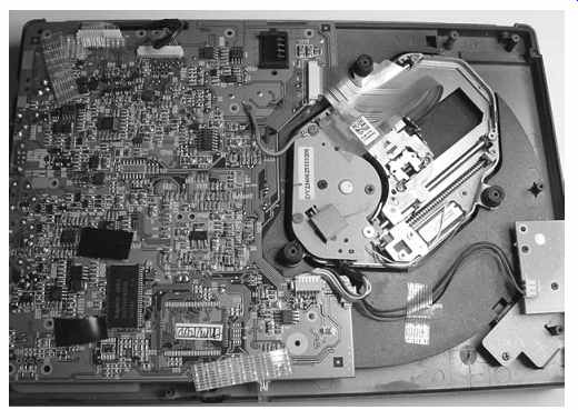
FIG. 3 Inside a portable DVD player
Portable DVD Players with LCD Screens
These usually have screws of varying lengths in the back. After you remove those, the back should come off, but make sure to have the unit lying on its face, because the laser sled assembly can fall out and tear its ribbon cables if you hold it in any other orientation. The assembly sits on rubber bumpers, and the back holds it in place. It's supposed to be loose, for vibration damping and skip resistance. See FIG. 3.
If you need to get to the LCD monitor and its associated circuitry, including the backlight inverter, its screws are probably under the rubber bumpers on each side at the top. Check the back of the LCD before peeling off the bumpers, though, in case the screws are back there. On many players, the plastic bezel will come off the front, with the LCD anchored to the back, but some are the other way around. Often, the speakers are on the bezel, connected by wires, so remove it carefully to avoid tearing them. If the bezel won't come off after you pull the screws, it either has internal snaps or is glued at the seam. Many of them are glued to prevent rattling from speaker vibrations. Use the snap-popping procedure described at the start of this Section. If you find no snaps, try gently peeling up the bezel one edge at a time. The feel of separating glue will be unmistakable. Just remember not to let the bezel pop off hard or you'll probably rip out those speaker wires. See FIG. 4.
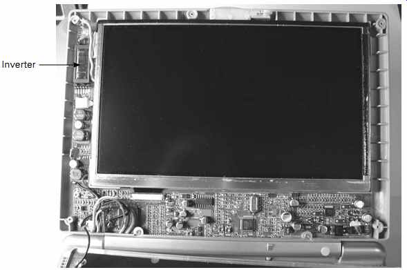
FIG. 4 LCD with bezel off.
MP3 Players
These vary quite a bit, depending on who makes them. Some come apart easily, with accessible screws, while others are snapped together tightly and require a shim tool to separate. If you don't see a way in, get on the Internet and look for disassembly instructions. You'll find them, at least for the most popular players.
Flash memory players are usually just one circuit board, with the display mounted to it. You'll probably need to get to the troublesome headphone or power jacks, so you'll have to remove the board unless all that's required is a resoldering of the jacks' contacts and the board happens to be oriented such that you can do the job in situ. If the player uses an internal battery, look for its connector and pull it before attempting repairs. As with other products, having power applied when you're working on the board can lead to circuit damage.
Hard drive players are a bit more complex, with a ribbon cable or two, and possibly more than one board. In most cases, it's best to remove the hard drive and put it aside. These units are more likely to have separate display boards, too, so be careful not to tear any ribbon cables when separating the case halves.
PDAs
These little handheld computers contain a remarkable number of parts, often on more than one board. You'll find a display, which also has the touch-sensitive digitizer, a rechargeable lithium battery, a main circuit board crammed with chips, and a switching-type power control and regulation system. Some PDAs have Wi-Fi and cameras, too, making for even more cables and boards.
The procedure for taking a PDA apart varies by maker, of course, but be prepared for a challenge. The keyword here is "small," so wear your magnifier. The multi-cup layer approach will be useful, as will taking photos as you go. Always keep the screen in mind, being careful not to scratch or press hard on it during your work. When you lay the product on its face, check your bench first for screws or parts that could damage the display.
Cell Phones
These are a lot like PDAs: lots of stuff in a very small space, with ribbons joining tiny keyboards and displays. Plus, there's an antenna on some that must be unscrewed and removed before the case can be separated. Be sure to take off the battery and pull the SIM (subscriber identity module) card as you begin. Be aware that the speaker magnet can attract tiny screws.
Camcorders
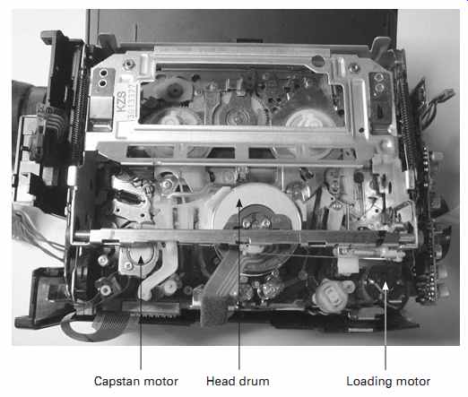
FIG. 5 Mechanism side of a camcorder: Capstan motor,Head drum, Loading motor
Camcorders that record to memory cards are like digital cameras, so see that section (next) for advice on taking them apart. Tape-based camcorders, analog or digital, are a whole 'nother story. These can rival laptop computers for complexity. In some ways they're worse because they are so oddly shaped that boards and mechanisms are crammed into nooks and crannies, making them hard to extricate. See FIG. 5.
Plus, the mechanism is delicate and easily damaged during disassembly. Drag out the cups and the digital camera.
If you only need to clean the heads, open the cassette door and then remove its two screws at the top. They may be under rubber covers. Take off the door and you should be all set.
For more extensive repairs, the machine will have to come apart. The typical camcorder body is in two pieces. Before you try to separate them, it's best to remove the cassette door, as it often prevents getting that side of the body off. If the machine works enough to get the door open, pop it open, take out its screws and remove the door. If the door is stuck closed, remove the screws anyway and see if you can slide off the door.
Most likely, it won't budge, but you might be able to remove it once the case is loose.
Look for arrows on the case indicating which screws need to come out. You may find screws all over the case, and most of them will have to go. On some cameras, various covers on the front and top have to come off because there are screws under them securing the shell to the chassis. Gently pull the two halves of the case apart, being careful not to get your fingers inside, where they could damage the mechanism.
You'll see ribbon cables all over the place, and you'll have to disconnect a few once the machine is apart.
Digital Cameras
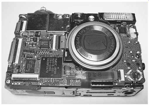
FIG. 6 Inside a digital camera
These are some of the hardest items to service. Most of today's cameras are very slim and small, and the works are crammed in there tightly. Plus, cameras have lots of buttons, and some have sliding switches with plastic parts that fall off into oblivion as the case comes apart.
The case halves on many digital cameras are three-dimensional puzzles. To get them apart, you may have to bend them around the edges slightly. On some, there's a plastic side piece surrounding the two halves, with tabs from each half fitting into it.
Generally, the back comes off, with all of the circuitry and the LCD remaining on the front. Be careful not to press on the LCD once the protective plastic window lifts off with the back of the case. See FIG. 6.
As mentioned awhile back, digital cameras store the energy for the flash tube in a large electrolytic capacitor. That baby can hold its charge of several hundred volts or more for weeks after its last use. Usually, the cap is stuffed under the main circuit board, next to the optical assembly. See FIG. 7. Its leads, however, may join the board just about anywhere. As you get the case apart, keep in mind that the connection to the flash cap could be right under your fingers. I've gotten zapped by digital cameras more often than by anything else. In addition to the danger to you, discharging the cap through your finger or a tool can leak high voltage into the camera's sensitive circuits, causing instant, silent damage.
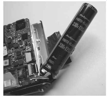
FIG. 7 The evil flash capacitor: note the voltage rating!
Laptop Computers
Laptops are among the most complex consumer devices and the toughest to take apart.
Talk about layers! You'll want to use the cups and camera for these. Before you begin, do an Internet search for disassembly instructions. Laptops are pretty trouble-prone, and sites abound with help. Very often, the disassembly sequence must be followed exactly or the machine can be damaged. Plus, where you begin depends on what area you need to reach. Changing the hard drive might require a different procedure and degree of disassembly than would resoldering the power jack or swapping out the backlight inverter.
Take off the battery before doing anything else. To remove the keyboard, look for snaps at the top. If you don't see any, check for screws on the bottom of the machine.
They'll nearly always be placed such that they screw into the back of the keyboard near its top. I've seen a few near the middle, but none at the bottom, which usually has slots fitting into grooves on the top half of the case. Once the keyboard is loose, pull it up gently, keeping in mind that a ribbon cable connects it.
If you're trying to repair a backlight problem, check on the Internet to determine where the inverter is before taking anything apart. Sometimes it's in the body of the machine, but it's more likely to be in the LCD housing. If it is, you might not need to open the rest of the laptop at all.
Most LCD housings are screwed together. Look for screws along the edges of the housing. If you don't find any, check for cosmetic covers or bumpers on the front, near the bottom of the LCD. I've seen a few cases where screws were under the rubber bumpers at the upper corners, but not many. Often, those bumpers are pretty permanently attached and will tear if you try to pull them out. Then you find there's nothing under them anyway. Before going that route, exhaust all other possibilities. Hidden snaps are common here too. Just avoid pressing on the screen; it's easy to do while pushing the seam along the edges, feeling for snaps.
Probably the most common failure in laptops is a loose, intermittent power jack.
Repair is simple: just resolder the jack to the motherboard. Alas, getting to it isn't always so easy. For this one, you'll need to take the case apart. Look for screws all over the back, and keep track of their lengths when you take them out. Watch for hidden snaps along the sides, and don't bend the back too hard or you can break the internal frame or the motherboard. Go easy.
Some models mount the board to the internal frame, while others have it screwed onto the back. Netbooks and lightweight notebooks don't always have frames. Instead, the major components are simply screwed to the back.
If you're lucky, the jack's solder connections will be visible, and you can resolder them without further disassembling the machine. If not, you may have to remove the top half of the case. Be very careful of ribbon connectors going to the trackpad and other items on the top half.
I recommend not trying to take apart a valuable laptop if you've never done it before, as the chance of wrecking it is substantial. Outdated machines are available for very little, or even for free, from online resources and local computer recyclers. Get one and practice on it.