

| Home | Articles | Forum | Glossary | Books |
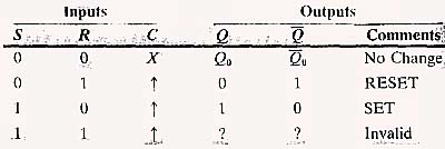
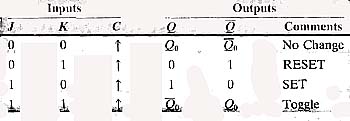
Questions1. Explain how NAND logic gates can be used to make an RS latch. 2. Provide an example of an industrial application that uses an RS latch and explain the operation of the application. 3. Explain the difference between a latch and a flip-flop. 4. Provide an example of an industrial application that uses a FIFO. 5. Explain the operation of a bit shift register. 6. Provide an example of an industrial application that uses a bit shift register. 7. Explain the difference between a bit shift register and a word shift register. 8. Provide an example of an industrial application that uses a word shift register. 9. Explain the operation of a ring counter. 10. Explain the operation of a Johnson counter. TRUE or FALSE1. ______ An RS latch will have an output at Q any time the S input is HI. 2. _______ An edge-triggered flip-flop will only change state when a pulse has transitioned the clock input. 3. _______ A shift register stores the value at the data input and shifts it to the right or left one bit each time a clock pulse is received. 4. ______ An edge-triggered flip-flop changes its output only when a clock pulse occurs at the clock input. 5. _______ The gray code is used in encoders because it has more bits than the binary code, which means it can count larger numbers. Multiple Choice1. The RS latch will provide an output at its Q output when____.
2. The edge-triggered JK flip-flop shown in Fig. 3 will have its Q output HI when___.
3. The ring counter uses ______
4. The motor starter coil for compressor 1 connected to the Q output of the edge-triggered JK flip-flop in Fig. 4 ______
5. A one-shot timer _______
Problems1. Sketch the diagram of an RS latch and identify its input and output terminals. 2. Sketch the truth table for an RS latch. 3. Draw a 555 timer used as a monostable vibrator and identify its inputs and outputs. 4. Sketch the diagram of an edge-triggered RS flip-flop and identify its input and output terminals. 5. Draw the symbol for on-delay timer contacts (delay on) and off-delay timer contacts (delay off) and explain how each operates. |
|
|
Solution to Job Assignment |
|
Home |