At first glance it may seem inappropriate to discuss industrial timers in a discussion on advanced solid-state logic. But upon closer examination, one should begin to notice that the same timer circuits that were previously discussed are typically found inside industrial timers. The major difference is that timers that are used in industrial applications must be designed to be easy to operate by someone who has little or no knowledge of solid-state logic. The person who adjusts the time setting for an industrial timer only understands the terms time delay-on and time delay-off. It’s also important for students who are studying to be industrial electronics technicians to understand that a completely different set of symbols is used for industrial timers. Since these symbols predate the electronics age, it may be of help to understand the early pneumatic timer and synchronous motor timers that the solid-state timers are replacing. It will be much easier to understand the solid-state circuits used in industrial timers if one understands the functions of time delay-on and time delay- off in industrial applications. Several industrial applications will be provided that use time delay-on and time delay-off symbols.
The second feature of industrial timers is that they should be able to handle the high temperatures and strong vibrations present on the factory floor. This means additional hardware may be added to the digital circuits one may be accustomed to working with. Industrial timers must also be capable of being interfaced to relay or solid-state logic circuits that require 24 volts ac or 120 volts ac.
This section will explain the four basic types of operators that provide time delay for industrial timers. The time-delay operators can be classified as pneumatic (air chamber), motor and cam, solid-state which may use simple time-constant circuits or more complex circuits like the 555 timer, or programmable timers that use microprocessors. The operation of each of these types of timers will be explained in this section with examples of common applications. Fig. 23 shows examples of industrial timers.
The electrical symbol for time-delay devices uses the head or tail of an arrow. The tail of the arrow is used to indicate time delay-on and the head of the arrow pointing down is used to indicate a time delay-off function. Fig. 24 shows examples of the time delay-on and the time delay-off symbols.
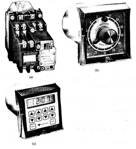
Above: Fig. 23: (a) A pneumatic industrial timer. (b) A motor-driven industrial timer. (c) A solid-state industrial timer.

Above: Fig. 24: Examples of time delay-on and time delay-off symbols.
On-Delay Timers
Industrial timers have contacts and an operator that cause the time delay. On-delay timers provide the function of changing the position of contacts after power is energized to the operator of the timer. Timers are widely used in industrial applications to control the starting time of larger motors so that they don’t all try to start at the same time. When a motor starts, it will draw a larger current than when it’s running at full speed. This starting current is called locked rotor amperage (LRA) or in-rush current and it’s caused by the armature not turning when power is first applied to the motor. As the motor shaft begins to rotate, the current drops to normal levels as the motor comes up to full speed. If a machine has several large hydraulic pump motors, they will all try to start at the same time when power is turned on. The starting cycle of the motors can be staggered by using on-delay timers so that the effects of in-rush current will be minimized.
The on-delay timer may also be called a delay-on timer. When power is applied to the motors, the first motor is allowed to start normally, but power to the second motor starter is controlled through the on-delay timer. If the timer is set for 10 seconds, the timer contacts will close after a 10-second delay. The time-delay period starts when power is applied to the time delay operator. Fig. 25 shows an example of this time delay-on circuit.

Above: Fig. 25: (a) Time delay-on timer used to delay the time two pump motors start to limit the effects of in-rush current. (b) Time delay-off timer used to delay the time a furnace fan stays on after the heating element is turned off. The additional time the fan runs allows extra heat to be re moved from the heating chamber.
Off-Delay Timers
In some applications it’s necessary to ensure that a motor continues to operate for several minutes after power is turned off to the main system. For instance, in large industrial heating systems, the fan may need to run for up to 2 minutes after the heating element or gas valve has been de-energized. The additional time the fan is allowed to run after the heat source is turned off will allow the system to capture all of the heat that has built up in the heating chamber and use it. This provides a degree of efficiency, since this heat would be lost if the fan was turned off at the same time as the heating element.
The time delay also prevents the heating system from overshooting the temperature setpoint on the controller. If the temperature setpoint is set for 1500 F, and the controller dc-energizes the heating element when the temperature reaches 150°, the heat that remains in the heating chamber would cause the system to overheat. The additional heat that remains in the chamber will act like a flywheel and continue to add heat to the application, which will cause the over-temperature condition.
The off-delay timer allows the heating control to dc-energize the heating element several degrees prior to the setpoint, and allows the fan to continue to operate for several additional minutes to dissipate the remaining heat. This type of timer control may also be called time delay-off timer. Fig. 25b shows an example of the time delay-off timer used to control the furnace fan.
Normally Open and Normally Closed Time-Delay Contacts
The time delay-on and the time delay-off timers can have normally open, normally closed, or both types of contacts. Fig. 26 shows the symbol for each of the four possible timers. This figure also shows a timing diagram for each type of timer contact.
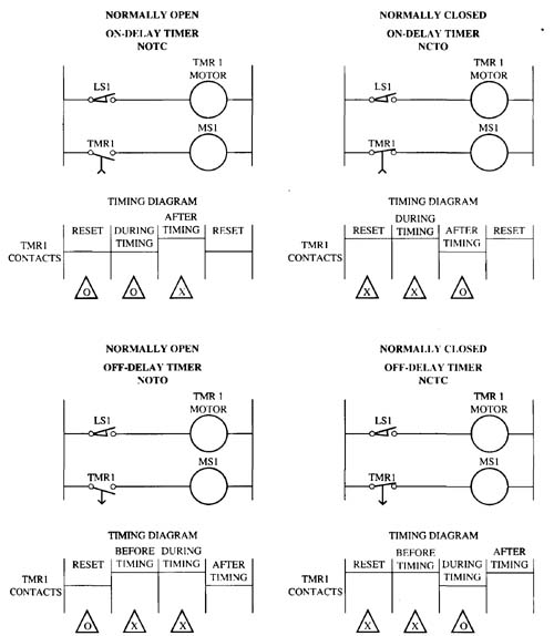
Above: Fig. 26: Symbols for the NOTC, NCTO, NOTO, and NCTC timers as they would be found in typical timing circuits. Timing diagrams are provided for each type of timer.
The on-delay timer can have normally open (NO) and normally closed (NC) contacts. The symbol for the on-delay timer with NO contacts is called normally open, timed close (NOTC). The contacts for this type of timer start out open and after the timing element is energized, the contacts will close after the time delay has elapsed. The symbol for the delay-on timer with NC contacts is called normally closed, timed open (NCTO). In Fig. 26 notice that the NOTC-type timer shows the contacts opening downward, and the tail of the arrow is used to indicate it’s an on-delay timer. The NCTO-type timer symbol shows the contact closed.
The timing diagram for each of the four types of timers is also shown in Fig. 26. The timing diagram shows the condition of the contacts as either open or closed during the four periods of the timer operation. The first timer period shows the contacts prior to timing. This represents the time before the timer operator is energized. The second period represents the time during timing, and the third period represents the time after timing, but power is still applied to the timer operator. The fourth period represents the time after timing when power is turned off to the operator. This condition is called reset and it actually occurs twice during the cycle, once at the very beginning of the cycle during the first timing period before timing, and again at the very end of the cycle. This means the very first part of the timing cycle may be called the time before timing, or reset. Also notice that the timing diagrams show a diagram for the timing operator as well as a diagram for each type of contact used. The diagram that shows power applied to the operator is provided as a reference to indicate when the timing cycle actually begins. The time-delay period for each timer should be counted from the point where power is applied to the time-delay operator.
The off-delay timer can also have NO and NC contacts. If the off-delay timer uses NO contacts, it will be called normally open, timed open (NOTO). The first question that comes to mind about this type of timer is how it can be normally open and then also timed open. The answer to this is explained by the omission of one of the states the off-delay timer goes through. The actual timing cycle for the off-delay timer includes three distinct steps: normally open, energized close, and then timed open. The timing diagram for this timer shows the contacts are normally open during the time prior to timing (reset). When power is initially applied to the circuit, the time-delay operator is powered and the NO contacts move to the closed position. When power to the time-delay operator is dc-energized, it will begin the time-delay period, and the contacts will open at the end of the timing period.
If the off-delay timer uses a closed set of contacts, it will be named normally closed, timed closed (NCTC). The name again seems to be contradictory because the contacts start out closed and end the cycle being timed closed. The part that is missing is the description of the middle part of the cycle where the contacts are opened when power is applied to the time-delay element. The on-delay and off- delay timers can have a single set of NO or NC contacts, or they can have multiple sets of both NO and NC contacts.
Pneumatic Timer Operators
Several different types of operators are used in industrial timers. The simplest type of operator is called a pneumatic operator. The pneumatic operator or element uses a bellows that fills with air. Prior to the start of the timing cycle, the bellows is completely filled with air, and when the time delay begins the air is released through a needle valve. The needle valve can be adjusted to regulate the time it takes for the air to move out of the bellows. A spring is mounted against the bellows to apply pressure to it to help force the air out. The amount of time it takes for the air to empty out of the bellows will determine the amount of time delay. When sufficient air has emptied out of the bellows, the spring pressure is strong enough to trip the mechanism that ends the timing cycle. The trip mechanism also actuates the timed contacts.
The pneumatic time-delay element is an add-on device to a traditional relay. Fig. 27 shows a picture of this type of add-on timing device. Since the pneumatic time-delay element is added to a normal control relay, this makes it possible to convert any control relay that is used in a circuit into a time-delay relay. Since the pneumatic element is added to the relay, it’s also possible to take advantage of the original relay contacts that will still operate with the relay coil. Since these contacts will open or close instantly when the coil is activated, they are called instantaneous contacts.
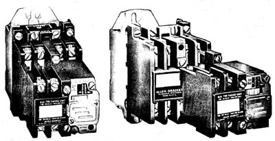
Above: Fig. 27: Pneumatic time-delay element. This element is added to a traditional relay to create a time-delay relay.
The pneumatic time-delay element can be converted from time delay-on to time delay-off right in the field. The element is designed so that when it’s mounted on the relay in the upright position, it will provide time delay-on functions. If the element is turned upside down when it’s mounted on the relay, it will provide time delay-off functions. One can determine if the element is mounted for delay-on or delay-off functions by looking closely at the lettering on the element. If the element is mounted for delay-on functions, the words on-delay will be visible rightside up, and the words off-delay will be visible upside down. When the element is mounted for off-delay functions, the words off-delay will be visible rightside up.
The time-delay element generally has two sets of contacts mounted on it. One set is usually normally open, and one set is normally closed. These contacts can be changed from normally open to normally closed or vice versa, by loosening a mounting screw and turning the contact set upside down. This provides the feature of changing the contacts in the field. One can determine if the set of contacts is normally open or normally closed by checking them with an ohmmeter.
Motor-Driven Timers
Motor-driven timers are widely used in industrial applications. These timers are also called synchronous motor timers or electromechanical timers. The timer uses a motor to turn a shaft on which cams are mounted. The shaft has a clutch that engages or disengages it to the motor. When the shaft is engaged (energized), the motor turns the shaft and the cams actuate several sets of contacts. When the time- delay period has elapsed, the time-delay contacts will change from open to closed or from closed to open, and the timer motor will reset for the next cycle. Fig. 27 shows a picture and diagram of a motor-driven timer.
From the diagram in Fig. 28, notice that the timer has a clutch coil and a motor connected in parallel with a common point identified as terminal 2. The timer has four sets of contacts. In the diagram contacts 9-10-C and 6-7-8 are located directly under the clutch coil to indicate they are energized instantaneously by the clutch when power is applied to the timer. Sets 11-12-A and 3-4-5 are located in the diagram directly under the timer motor to indicate they are controlled by the timer motor. These contacts are called the delay contacts.
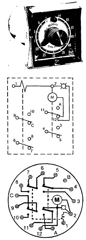
Above: Fig. 28: Synchronous motor-driven timer with a diagram of the internal electric contacts circuit.
A second diagram is provided in Fig. 28 that shows a terminal diagram for the timer. In a typical application a limit switch is used to control the timer. When the limit switch is closed, power is applied through it to the clutch coil. This same power energizes the motor, but it must go through NC time-delay contacts 11-12. When power reaches the clutch coil, it immediately activates the instantaneous contacts and engages the clutch. Power also reaches the timer motor and it begins to rotate its shaft. Since the clutch is engaged, the motor shaft turns the time-delay shaft and when the correct amount of time delay has passed, the cams located on the shaft will move with the shaft and activate both sets of time-delay contacts. Since the timer motor is connected through the NC set of time-delay contacts 11-12, the timer motor will become de-energized when the contacts open and the timer will be reset and ready for the next cycle. The instantaneous sets of contacts controlled by the clutch coil will remain energized until the limit switch is de-energized.
Using Time Delay to Control Pouring Gray Iron
An example of the time-delay circuit in an industrial application controls an automatic continuous pouring of cast iron into sand molds moving along a conveyor ( see Fig. 29). This foundry application is used to provide control of the continuous pouring line that makes brake rotors for automobiles. The sand molds for the brake rotors are made by an automatic molding machine that sets each finished mold on a conveyor line.
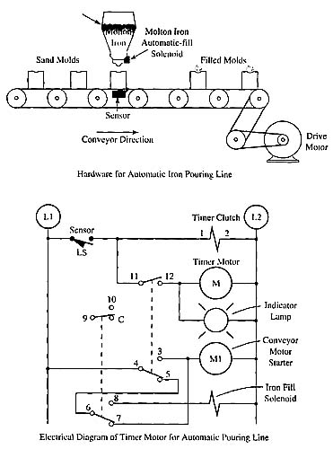
Above: Fig. 29: Example application of a motor- driven timer used to control pouring gray iron into sand molds passing by on a conveyor line.
The molds move along the conveyor line until they reach the pouring station where they will trip a photoelectric switch that controls a timer. Notice that the motor starter for the conveyor motor is connected in series with the 4-5 NC delay contacts and the 6-7 NC instantaneous contacts.
When the mold moves into place under the pouring system, the photoelectric switch will activate the timer and the NC 6-7 instantaneous contacts will open and dc-energize the conveyor motor starter, which stops the conveyor immediately. The instantaneous 6-7 contacts will switch to the 6-8 position, which will energize the pouring system solenoid. The pouring system solenoid controls a large gear box that tips a ladle into position so that gray iron fills the mold. The amount of time delay is adjusted so that the sand mold is filled to the top. When the amount of time delay expires, the timed 4-5-3 contacts will change from the normally closed 4-5 position to the 4-3 position, which will energize the conveyor motor starter again.
When the motor starter is energized again, the conveyor will begin to move the mold so that it no longer breaks the photoelectric beam. The conveyor continues to move until the next mold on it blocks the photoelectric switch light beam, which activates the process again. Some automatic pouring lines use laser detectors to monitor sprue holes or vent holes in the top of the sand mold to ensure the mold fills completely with molten gray iron during the pouring process. When molten iron appears in the vent hole, the mold is completely filled and the laser control can stop the pouring operation before the time delay elapses. The laser control provides a safety backup to the timer in case the molds fill too quickly.
Off-Delay Timers
The motor-driven timer cannot provide both on-delay and off-delay functions from the same device. If an off-delay function is required, a separate timer must be used. This timer is called a reverse-acting timer. That is, one must determine the type of timer one needs before one purchases it. If you have a timer in the stockroom you can tell if it’s an on-delay or off-delay timer by closely inspecting the clutch mechanism. An on-delay timer has a normally open clutch, and the clutch for the reverse-acting off-delay timer is normally closed.
Solid-State Time-Delay Devices
A wide variety of solid-state timers is available for industrial applications. These timers range from the simplistic and inexpensive resistive-capacitive (RC) time- constant timers to the more elaborate CMOS-type timers. These timers provide a set of terminals where an external resistor (potentiometer) can be connected to provide a means of adjusting the time delay remotely. The amount of resistance in the RC time-constant timers will determine the amount of time delay. Some of the timers will provide a knob directly on the timer that allows the amount of time delay to be set locally, while other inexpensive timers provide a fixed amount of time delay that must be determined prior to purchase.
Fig. 30 shows examples of several solid-state timers. The solid-state timer is also available as an add-on element similar to the pneumatic element. This allows the solid-state timing element to be added directly to a traditional control relay. The solid-state timers shown in Fig. 30 are available with a variety of outputs.
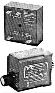
Above: Fig. 30: Solid-state time delay devices. The inexpensive solid-state devices use RC time-constant technology, and the more ex pensive types use CMOS technology.
Since these devices are solid state, they can provide outputs that include delay-on make (on-delay), delay-on brake (off-delay), repeat cycle, interval cycle, and single shot. Other types of solid-state time-delay devices provide thumbwheels on the front of the device that allow the amount of time delay to be set as a value.
Programmable Timers
The newest types of time-delay devices are microprocessor-based programmable timers. These devices utilize all of the features of a microprocessor, which include a keypad for input and light-emitting diode (LED) display. The amount of time delay and the type of outputs are all programmable through the keypad. The operation of the timer function such as pulse cycle, repeat cycle, or single shot is also programmable. Fig. 31 shows an example of the microprocessor-based programmable timer.
Since the function of counting is very similar to timing, the programmable type timer can be programmed to operate as a time-delay device or as a counter. This feature provides industry the ability to purchase and stock one device for use as a timer or counter.
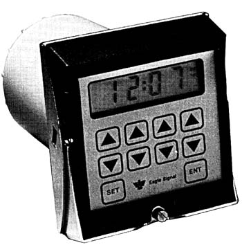
Above: Fig. 31: Microprocessor-based programmable-type timer. This device can be programmed to provide on-delay, off-delay, and counting functions. This allows one device to be stocked that can be programmed at the time of installation to provide multiple functions.

