AMAZON multi-meters discounts AMAZON oscilloscope discounts
The stator is the stationary part of the motor and is made of several parts. Fig. 1 shows the stator of a typical induction motor. The stator is the frame for the motor housing the stationary winding with mounting holes for installation. The mounting holes for the motor are sized according to NEMA standards for the motor’s frame type. Some motors will also have a lifting ring in the stator to provide a means for handling larger motors. The lifting ring and mounting holes are actually built into the frame or housing part of the stator.
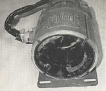
Above: Fig. 1 Example of a typical stator for an AC motor.
An insert is set inside the stator that provides slots for the stator coils to be inserted into. This insert is made of laminated steel to prevent eddy current and flux losses in the coils. The stator windings are made by wrapping a predetermined length of wire on preformed brackets in the shape of the coil. These windings are then wrapped with insulation and installed in the stator slots. A typical four-pole. three-phase motor will have three coils mounted consecutively in the slots to form a group. The three coils will be wired so that they each receive power from a separate phase of three-phase power supply. Three groups are connected together to form one of the four poles of the motor. This grouping is repeated for each of the other three poles so that the motor has a total of 36 coils to form the complete four-pole stator. It's not essential that one understands how to wind the coils or put them into the stator slots; instead, one should understand that these coils are connected in the stator, and 3, 6, 9, 12, or 15 wires from the coil connections will be brought out of the frame as external connections. The external connection wires can be connected on the factory floor to allow the motor to be powered by 208/ 230 or 480 volts, or they allow the motor to be connected to provide the correct torque response for the load. Other changes can also be made to these connections to allow the motor to start so it uses less locked-rotor current.
After the coils are placed in the stator, their ends (leads) will be identified by a number that will be used to make connections during the installation procedure. The coils are locked into the stator with wedges that keep the coils securely mounted in the slots and allow them to be removed and replaced easily if the coils are damaged or become defective due to overheating.