The capacitor start, capacitor run motor is used primarily in starting
large single- phase hermetic compressors. Since the hermetic motor can't use an end switch. a starting relay similar to the current relay must
he used. The current relay requires that its coil be connected in series
with the run winding of the compressor motor. In the CSCR motor, the
run current can he exceedingly large when the motor is starting (LRA).
This current is too large for the current relay coil and would tend to
burn it out. For this reason a different type of starting relay, which
senses the amount of counter EMF for actuation, is used to start the
CSCR motor. Since this relay uses the difference of potential between
the applied voltage and the counter EMF produced by the rotor, it's called
a potential relay.
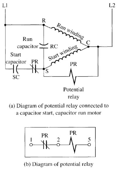
Fig. b (right) shows a diagram of a potential relay. Notice that its terminals are identified as 1, 2, and 5. It has an NC set of contacts between terminals I and 2 and a high-resistance coil between terminals 2 and 5. The diagram in Figure 1a shows the potential relay connected to a motor with a start and run capacitor.
Note that the potential relay’s contacts are connected in series with the start capacitor and the motor’s start winding. The run capacitor is connected between the S and R terminals of the motor, where it will remain even when the motor is running. Also notice the dot on the curved side of the capacitor symbol, it represents the side of the run capacitor that should he connected to the line side of the power supply. This dot corresponds to a red mark on one of the run capacitor terminals. This terminal is marked because it's the terminal that is closest to the outside of the metal can that the capacitor is mounted in. If the capacitor is shorting out, it will short to this side of the circuit and cause a fuse to blow and the motor would not he damaged. If this capacitor is connected in the circuit so that the identified terminal is connected to the start winding, short- circuit current would he drawn through the motor windings and the motor would be damaged.
The operation of the potential relay is controlled by the amount of counter EMF that the rotor produces. When voltage is applied to the motor through L1 and L2, the run winding is energized directly and the start winding is powered through the start capacitor and NC set of contacts of the potential relay. The applied voltage is not strong enough to activate the potential relay’s coil.
When the motor starts and the rotor begins to spin, a counter EMF is produced between motor terminals S and C. The counter EMF will become large enough to energize the potential relay coil when the motor reaches approximately 75% rpm. When the coil is energized, it pulls its NC contacts open, which dc-energizes the start capacitor and start winding. This effectively removes the start winding from the source of applied voltage.
The run capacitor is connected to the R and S terminals on the motor so that it's in circuit between the run winding and the start winding and will allow a very small amount of current to flow through from L1 to the start winding. When the load increases, such as when the compressor must pump more refrigerant, the rotor will begin to slow down and the counter EMF will be reduced slightly. This allows the run capacitor to provide a small phase shift, as it adds more current to the start winding. This increased current with the phase shift provides additional torque and the rotor’s speed will again be increased to full rpm. This allows the CSCR motor to operate at a fairly constant speed. The CSCR motor is not used in open motor applications, but the run capacitor concept is used frequently in a motor called the permanent split-capacitor motor.