AMAZON multi-meters discounts AMAZON oscilloscope discounts
A start capacitor is connected in series with the start winding of the CSIR motor to provide a larger phase shift when voltage is first applied to the motor. The increased phase shift causes a stronger magnetic field to pull on the rotor to cause it to begin to spin. The electrical diagram for the CSIR motor connected for forward rotation and for reverse rotation is provided in Fig. 1. The start capacitor is usually rated for over 100 microfarads (up to 1000 uF).
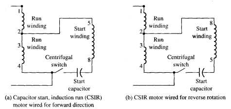
Above: Fig. 1: (a) Electrical diagram of a capacitor start, induction
run (CSIR) motor connected for forward rotation. (b) Electrical diagram
of a CSIR motor connected for reverse rotation. on.
The start capacitor can provide large amounts of capacitance for a short period of time, such as during starting. After the motor is started, the capacitor must be removed from the circuit so that it won't overheat. This is accomplished with the end switch. The electrical diagram in this figure shows the capacitor connected in series with the start winding. When voltage is first applied to the motor, both the start winding and the run winding will be energized. When the rotor reaches nearly full rpm, the end switch will open and disconnect the start winding and capacitor from the circuit. That is, no current will flow through either the start winding or the capacitor and they can cool down and be ready for the next time the motor is started. When the motor is de-energized and the rotor slows to a stop, the end switch is closed again and the start winding and capacitor are reconnected to the circuit for the next start.
Since the start capacitor is physically mounted on top of the motor, a metal cover is placed over it to protect it from damage. Since the capacitor’s case is made of plastic, it can easily be cracked and damaged if the motor is used in a harsh industrial environment.