AMAZON multi-meters discounts AMAZON oscilloscope discounts
The stator is the frame of the motor which houses the windings. Since the single phase motor uses single-phase voltage, it will need a way to produce the starting torque that three-phase voltage produces naturally in a three-phase motor. The single-phase motor has a special starting winding that is used to provide sufficient phase shift to provide starting torque. The motor also has a run winding that is similar to the windings in a three-phase motor. The start winding is made of very fine gauge wire, which has many more turns than the run winding. The run winding is made from wire that is sized to carry the current for the motor at full-load amperage ( FLA). This means the run winding wire will be much larger than the start winding and usually in the range of 12- to 16-gauge wire.
The start winding is also placed in the stator offset from the run winding to give a larger phase difference. This physical phase shift will enhance a shift in the magnetic field produced by two windings. Since the start winding is made of very fine wire that has many turns, it can produce a strong magnetic field for a short period of time. Fig. 1a shows the locations of the start and run windings in the stator. note that four run and four start windings are shown inside the stator. The start windings are shown located toward the inside of the stator, where they will be closer to the rotor, and the run winding is shown placed behind the start winding. The start and run windings are connected together in parallel in the motor to provide the magnetic phase shift.
Several electrical diagrams are also presented in this figure to show methods of representing the single-phase motor. In Fig. 1b the windings are shown placed at right angles to each other. This is done remind one that the windings are physically offset in the stator to produce more of a magnetic phase shift. Note that the run winding is always represented by the larger coil and its terminals are numbered 1 and 4. The start winding is shown as the smaller coils and its terminals are numbered 5 and 8. The rotor is shown in these diagrams as a circle in the middle of the windings.
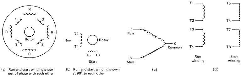
Above: Fig. 1: (a) Diagram of start and run winding locations inside
the motor stator. (b) Diagram that shows the start winding placed at
900 to the run winding in the stator. (c) Diagram that shows one end
of the start and run windings connected together at a point called common
(C). (d) The run winding is shown in two parts and the start winding
is shown in two parts. Click here
for large-sized image.
In Fig. 1c the windings are shown connected in parallel with each other, which is how one would indicate their electrical relationship. Note that in this diagram the run winding is identified with the letter R and the start winding is identified with the letter S. The point where the two windings are connected at the bottom end of the parallel circuit is called the common point and is identified by the letter C. In some motor theory, it's referred to as terminal C, even though it's the point where the two windings are connected together. This type of diagram is used frequently to show the windings of single-phase compressor motors used in air-conditioning systems.
Fig. 1d show the windings of a single-phase motor as one would normally see them in diagrams of open-type motors that are used to power small machines in a factory. The windings are shown as two sets. The run winding is shown in two parts. The first part is a winding that is identified by terminal numbers T1 - T2, and the second part is identified as T3 and T4. The run winding consists of two parts so that the motor can be connected for high voltage (230 volts) or low voltage (115 volts). If the motor is connected for high voltage, the two parts of the run winding are connected in series, and if the motor is connected for low voltage, the two run windings are connected in parallel. A detailed discussion of high- and low-voltage connections will be presented later in this section.
The start winding is also shown in two parts in Fig. 1d. In this diagram notice that the first segment of the start winding is identified as terminals T5 and T6 and the second set is identified as terminals T7 and T8. If T6 and T7 are permanently connected inside the motor, the two ends of the start winding will be identified as T5 and T8.