| Home | Articles | Forum | Glossary | Books |
|
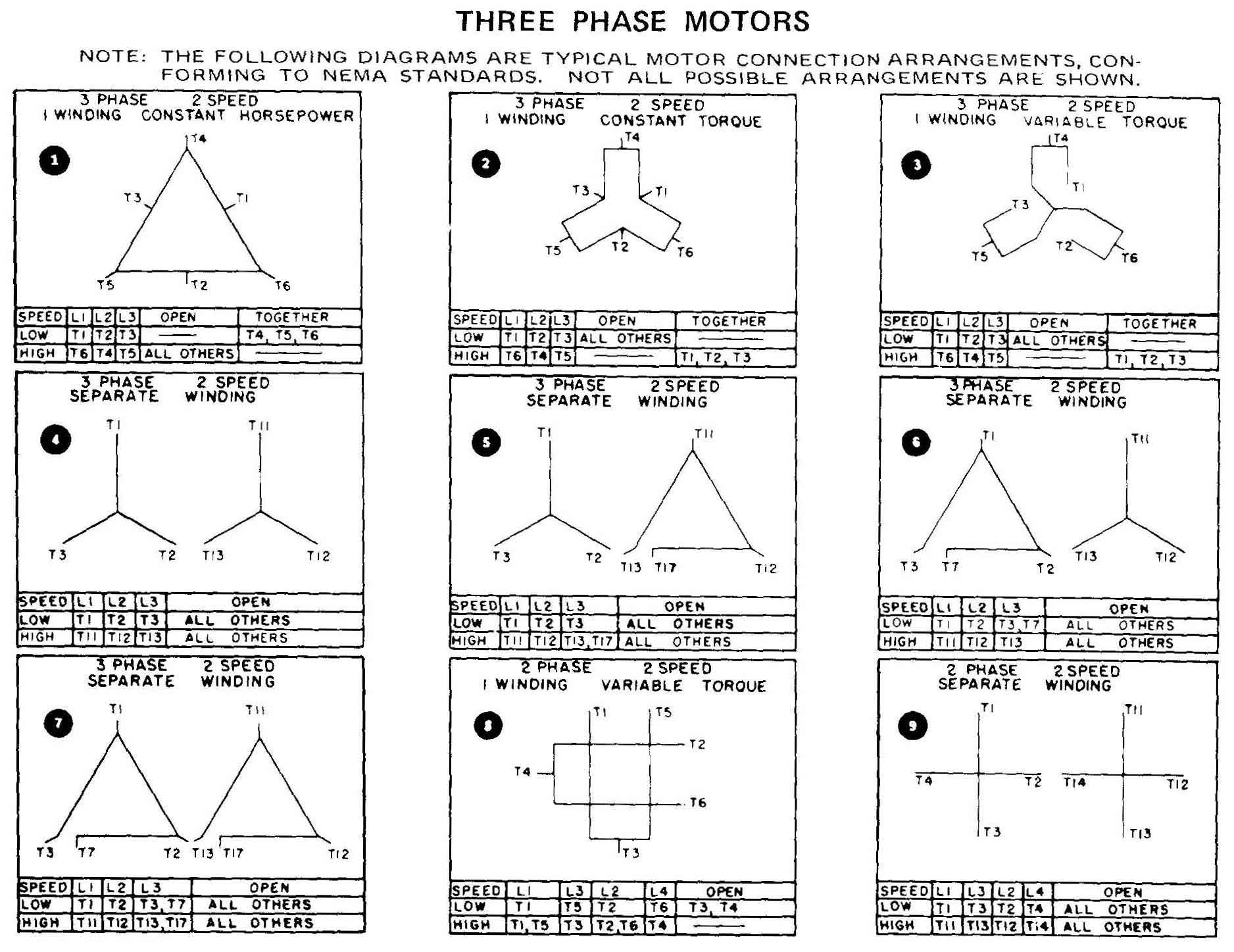
AMAZON multi-meters discounts AMAZON oscilloscope discounts The diagrams in this figure show two ways of representing the connections that must be made to the motor terminals. One way shows the connections with an electrical diagram. and the second way is to show a table that indicates which terminal numbers should he connected. When one is ready to make the motor connections, note that the terminals in the motor are marked with numbers which are stamped into the wire material, or identified with a metal tag that has a number on it. The metal tag is crimped on each wire near the terminal end. After one has located all the terminals and have identified them by their numbers, one is ready to make the connections shown in the diagram for your application. The table lists the terminals that should be connected to the three input- voltage wires. These are identified as L1, L2, and L3, and any terminal number listed in the category under the line number should be connected to that line. Be sure to check the row indicating the speed for which the motor will he wired. The second column lists the wires that are left open. That is, the wires listed in this column shouldn't be connected to anything. They are supposed to remain unconnected and they should have an insulated wire nut or cap placed over the end of the wire securely so that it does not come in contact with any metal parts of the motor or other energized wires. In some tables any lead that is not listed in another column should be left open. The third column lists the leads or wires that should be connected together. In other words, the wires listed in this column should be connected together and no power should he connected to these leads. The leads must he secured together with a wire nut and wrapped with insulating tape because they will be energized. In some diagrams no terminals will he listed in this column, which means that all the leads are used in one of the other columns. Be certain to account for every lead before returning all the leads back into the motor and replace the field wiring access cover. These diagrams are extremely useful when the application one is working with requires the motor to be reconnected on the factory floor. Many times these diagrams are not readily available when one needs them, so this provides that much needed reference. These motors can also be reversed by exchanging two of the three supply voltage lines. This allows the motors to he used in the widest possible number of applications. If you're a technician, it's important to realize that you'll be required to make these changes yourself or direct someone to make them for you. So you must understand the concept of changing the connections of motor leads to make the motor fit the application. |
| Connecting Motors for a Change Of Voltage | Motor Data Plates | Home |