AMAZON multi-meters discounts AMAZON oscilloscope discounts
SPECIFIC LOADINGS and SPECIFIC OUTPUT
Specific loadings
A design compromise is inevitable in the crucial air-gap region, and designers constantly have to exercise their skills to achieve the best balance between the conflicting demands on space made by the flux (radial) and the current (axial).
As in most engineering design, guidelines emerge as to what can be achieved in relation to particular sizes and types of machines, and motor designers usually work in terms of two parameters, the specific magnetic loading, and the specific electric loading. These parameters have a direct bearing on the output of the motor, as we will now see.
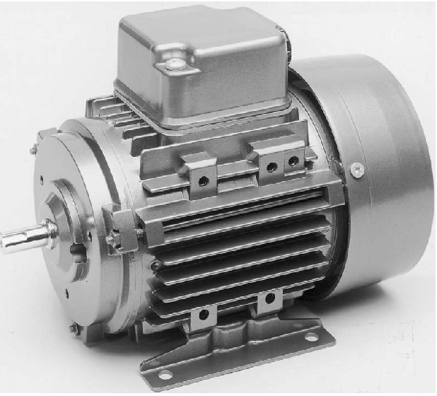
Totally enclosed fan-ventilated (TEFV) cage
induction motor. This particular example is rated at 200 fi (0.27 h.p.)
at 1450 rev/min, and is at the lower end of the power range for 3-phase
versions. The case is of cast aluminum, with cooling air provided by
the covered fan at the non-drive end. Note the provision for alternative
mounting.
The specific magnetic loading (B) is the average of the magnitude of the radial flux density over the entire cylindrical surface of the rotor. Because of the slotting, the average flux density is always less than the flux density in the teeth, but in order to calculate the magnetic loading we picture the rotor as being smooth, and calculate the average flux density by dividing the total radial flux from each 'pole 'by the surface area under the pole.
The specific electric loading (usually denoted by the symbol (A), the A standing for Amperes)is the axial current per meter of circumference on the rotor. In a slotted rotor, the axial current is concentrated in the conductors within each slot, but to calculate A we picture the total current to be spread uniformly over the circumference (in a manner similar to that shown in ill. 12,but with the individual conductors under each pole being represented by a uniformly distributed 'current sheet'). E.g., if under a pole with a circumferential width of 10 cm we find that there are five slots, each carrying a current of 40 A, the electric loading is
5 x 40 / 0.1 = 2000 A/m.
Many factors influence the values which can be employed in motor design, but in essence the specific magnetic and electric loadings are limited by the properties of the materials (iron for the flux, and copper for the current),and by the cooling system employed to remove heat losses.
The specific magnetic loading does not vary greatly from one machine to another, because the saturation properties of most core steels are similar. On the other hand, quite wide variations occur in the specific electric loadings, depending on the type of cooling used.
Despite the low resistivity of the copper conductors, heat is generated by the flow of current, and the current must therefore be limited to a value such that the insulation isn't damaged by an excessive temperature rise. The more effective the cooling system, the higher the electric loading can be. E.g., if the motor is totally enclosed and has no internal fan, the current density in the copper has to be much lower than in a similar motor which has a fan to provide a continuous flow of ventilating air. Similarly, windings which are fully impregnated with varnish can be worked much harder than those which are surrounded by air, because the solid body of encapsulating varnish pro vides a much better thermal path along which the heat can flow to the stator body. Overall size also plays a part in determining permissible electric loading, with large motors generally having higher values than small ones.
In practice, the important point to be borne in mind is that unless an exotic cooling system is employed, most motors (induction, d.c. etc.) of a particular size have more or less the same specific loadings, regardless of type. As we will now see, this in turn means that motors of similar size have similar torque capabilities. This fact isn't widely appreciated by users, but is always worth bearing in mind.
Torque and motor volume
In the light of the earlier discussion, we can obtain the total tangential force by first considering an area of the rotor surface of width w and length L .The axial current flowing in the width w is given by I = wA , and on average all of this current is exposed to radial flux density B ,so the tangential force is given (from equation 1.2) by B x wA x L .The area of the surface is wL ,so the force per unit area is B x A .We see that the product of the two specific loadings expresses the average tangential stress over the rotor surface.
To obtain the total tangential force we must multiply by the area of the curved surface of the rotor, and to obtain the total torque we multiply the total force by the radius of the rotor. Hence for a rotor of diameter D and length L ,the total torque is given by
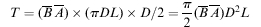
(1. 9)
This equation is extremely important. The term D2 L is proportional to the rotor volume, so we see that for given values of the specific magnetic and electric loadings, the torque from any motor is proportional to the rotor volume. We are at liberty to choose a long thin rotor or a short fat one, but once the rotor volume and specific loadings are specified, we have effectively determined the torque.
It is worth stressing that we have not focused on any particular type of motor, but have approached the question of torque production from a completely general viewpoint. In essence our conclusions reflect the fact that all motors are made from iron and copper, and differ only in the way these materials are disposed. We should also acknowledge that in practice it's the overall volume of the motor which is important, rather than the volume of the rotor. But again we find that, regardless of the type of motor, there is a fairly close relationship between the overall volume and the rotor volume, for motors of similar torque. We can therefore make the bold but generally accurate statement that the overall volume of a motor is deter mined by the torque it has to produce. There are of course exceptions to this rule, but as a general guideline for motor selection, it's extremely useful.
Having seen that torque depends on rotor volume, we must now turn our attention to the question of power output.
Specific output power--importance of speed
Before deriving an expression for power, a brief digression may be helpful for those who are more familiar with linear rather than rotary systems.
In the SI system, the unit of work or energy is the Joule (J).One joule represents the work done by a force of 1 newton moving 1 meter in its own direction. Hence the work done (W) by a force F which moves a distance d is given by
W = F x d
With F in newtons and d in meters, W clearly in newton-meters (Nm), from which we see that a newton-meter is the same as a joule.
In rotary systems, it's more convenient to work in terms of torque and angular distance, rather than force and linear distance, but these are closely linked as we can see by considering what happens when a tangential force F is applied at a radius r from the centre of rotation. The torque is simply given by
T = F r
Now suppose that the arm turns through an angle alpha, so that the circumferential distance travelled by the force is r x alpha .The work done by the force is then given by
W = F (r x θ) = (F r) x θ = T x θ (1.10)
We note that whereas in a linear system work is force times distance, in rotary terms work is torque times angle. The units of torque are newton-meters, and the angle is measured in radians (which is dimensionless), so the units of work done are Nm, or Joules, as expected. (The fact that torque and work (or energy) are measured in the same units does not seem self-evident to this author!) To find the power, or the rate of working, we divide the work done by the time taken. In a linear system, and assuming that the velocity remains constant, power is therefore given by
P = W/t = F x d / t = F v ( 1.11)
where v is the linear velocity. The angular equivalent of this is given by
P = W/t = T x θ / t = T x ω (1.12)
where v is the (constant)angular velocity, in radians per second.
We can now express the power output in terms of the rotor dimensions and the specific loadings, using equation 1.9 which yields
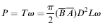
(1.13)
Equation 1.13 emphasizes the importance of speed in determining power output. For given specific and magnetic loadings, if we want a motor of a given power we can choose between a large (and therefore expensive) low-speed motor or a small (and cheaper) high-speed one. The latter choice is preferred for most applications, even if some form of speed reduction (using belts or gears) is needed, because the smaller motor is cheaper. Familiar examples include portable electric tools, where rotor speeds of 12000 rev/min or more allow powers of hundreds of watts to be obtained, and electric traction: wherein both cases the high motor speed is geared down for the final drive-In these examples, where volume and weight are at a premium, a direct drive would be out of the question.
The significance of speed is underlined when we rearrange equation 1.13 to obtain an expression for the specific power output (power per unit rotor volume), Q ,given by

( 1.14)
To obtain the highest possible specific output for given values of the specific magnetic and electric loadings, we must clearly operate the motor at the highest practicable speed. The one obvious disadvantage of a small high-speed motor and gearbox is that the acoustic noise (both from the motor itself and the from the power transmission) is higher than it would be from a larger direct drive motor. When noise must be minimized (for example in ceiling fans), a direct drive motor is therefore preferred, despite its larger size.
Wiki Series: Laboratory Manual for Electronics
Three-Phase Transformers
Objectives
- Connect three single-phase transformers to form a three-phase bank.
- Connect transformer windings in a delta configuration.
- Connect transformer windings in a wye configuration.
- Compute values of voltage, current, and turns-ratio for different three-phase connections.
- Compute the values for an open delta connected transformer bank.
Three-phase transformers are used throughout industry to change values of three-phase voltage and current. Since three-phase power is the major way in which power is produced, transmitted, and used, an understanding of how three-phase transformer connections are made is essential. This unit discusses different types of three-phase transformer connections and presents examples of how values of voltage and current for these connections are computed.
A three-phase transformer is constructed by winding three single-phase transformers on a single core, as shown in ill. 1. The transformer is enclosed in a case and may be dry or mounted in an enclosure that will be filled with a dielectric oil. The dielectric oil performs several functions. Since it's a dielectric, it provides electrical insulation between the windings and the case. It is also used to help provide cooling and to prevent the formation of moisture, which can deteriorate the winding insulation.
ill. 1 Basic construction of a three-phase transformer.
ill. 2 Wye-delta connected three-phase transformer.
ill. 3 Delta-wye connected three-phase transformer.
Three-Phase Transformer Connections
Three-phase transformers are connected in delta or wye configurations. A wye-delta transformer, for example, has its primary winding connected in a wye and its secondary winding connected in a delta, as shown in ill. 2. A delta-wye transformer would have its primary winding connected in delta and its secondary connected in wye, as shown in ill. 3.
ill. 4 Identifying the windings.
Connecting Single-Phase Transformers into a Three-Phase Bank
If three-phase transformation is needed, and a three-phase transformer of the proper size and turns-ratio isn't available, three single-phase transformers can be connected to form a three-phase bank. When three single-phase transformers are used to make a three phase transformer bank, their primary and secondary windings are connected in a wye or delta connection. The three transformer windings in ill. 4 have been labeled A, B, and C. One end of each primary lead has been labeled H1 and the other end has been labeled H2. One end of each secondary lead has been labeled X1 and the other end has been labeled X2.
ill. 5 Three single-phase transformers.
ill. 5 shows three single-phase transformers labeled A, B, and C. The primary leads of each transformer have been labeled H1 and H2, and the secondary leads have been labeled X1 and X2. The schematic diagram of ill. 4 will be used to connect the three single phase transformers into a three-phase wye-delta connection as shown in ill. 6.
The primary winding will be tied into a wye connection first. The schematic in ill. 4 shows that the H2 lead of each primary winding is connected together, and the H1 lead of each winding is open for connection to the incoming power line. Notice in ill. 6 that the H2 lead of each primary winding has been connected together, and the H1 lead of each winding has been connected to the incoming power line.
ill. 6 Connecting three single-phase transformers to form a wye-delta three-phase bank.
ill. 4 also shows the X1 lead of transformer A is connected to the X2 lead of transformer C.
Notice that this same connection has been made in ill. 6. The X1 lead of transformer B is connected to the X2 lead of transformer A, and the X1 lead to transformer C is connected to the X2 lead of transformer B. The load is connected to the points of the delta connection.
Although ill. 4 illustrates the proper schematic symbology for a three-phase transformer connection, some electrical schematics and wiring diagrams don't illustrate three phase transformer connections in this manner. One type of diagram, called the one line diagram, would illustrate a delta-wye connection as shown in ill. 7. These diagrams are generally used to show the main power distribution system of a large industrial plant.
The one line diagram in ill. 8 shows the main power to the plant and the trans formation of voltages to different subfeeders. Notice that each transformer shows whether the primary and secondary are connected as a wye or delta, and the secondary voltage of the subfeeder.
ill. 7 One line diagram symbol used to represent a delta-wye three-phase transformer connection.
ill. 8 One line diagrams are generally used to show the main power distribution of a plant.
ill. 9 Testing for proper transformer polarity before closing the delta.
Closing a Delta
Delta connections should be checked for proper polarity before making the final connection and applying power. If the phase winding of one transformer is reversed, an extremely high current will flow when power is applied. Proper phasing can be checked with a voltmeter as shown in ill. 9. If power is applied to the transformer bank before the delta connection is closed, the voltmeter should indicate 0 volt. If one phase winding has been reversed, however, the voltmeter will indicate double the amount of voltage. E.g., assume the output voltage of a delta secondary is 240 volts. If the voltage is checked before the delta is closed, the voltmeter should indicate a voltage of 0 volt if all windings have been phased properly. If one winding has been reversed, however, the voltmeter will indicate a voltage of 480 volts (240 + 240). This test will confirm whether a phase winding has been reversed, but it won't indicate if the reversed winding is located in the primary or secondary. If either primary or secondary windings have been reversed, the voltmeter will indicate double the output voltage.
It should be noted, however, that a voltmeter is a high impedance device. It isn't unusual for a voltmeter to indicate some amount of voltage before the delta is closed, especially if the primary has been connected as a wye and the secondary as a delta. When this is the case, however, the voltmeter will generally indicate close to the normal output voltage if the connection is correct and double the output voltage if the connection is incorrect. Regardless of whether the primary is connected as a delta or wye, the voltmeter will indicate twice the normal output voltage of the secondary if the connection is incorrect.
Three-Phase Transformer Calculations
When computing the values of voltage and current for three-phase transformers, the formulas used for making transformer calculations and three-phase calculations must be followed.
Another very important rule that must be understood is that only phase values of voltage and current can be used when computing transformer values. When three-phase transformers are connected as a wye or delta, the primary and secondary windings themselves become the phases of a three-phase connection. This is true whether a three-phase transformer is used or whether three single-phase transformers are employed to form a three phase bank. Refer to transformer A in ill. 5. All transformation of voltage and current takes place between the primary and secondary windings. Since these windings form the phase values of the three-phase connection, only phase, not line, values can be used when calculating transformed voltages and currents.
Helpful Hint: Only phase values of voltage and current can be used when computing transformer values.
Example #1: A three-phase transformer connection is shown in ill. 10. Three single phase transformers have been connected to form a wye-delta bank. The primary is connected to a three-phase line of 13,800 volts, and the secondary voltage is 480. A three-phase resistive load with an impedance of 2.77 ohm per phase is connected to the secondary of the transformer. The following values will be computed for this circuit.
ill. 10 Example #1: Three-phase transformer calculations.
E_P(PRIMARY) = Phase voltage of the primary
E_P(SECONDARY) = Phase voltage of the secondary
Ratio = Turns-ratio of the transformer
E_P(LOAD) = Phase voltage of the load bank
IP(LOAD) = Phase current of the load bank
I_L(SECONDARY) = Secondary line current
I_P(SECONDARY) = Phase current of the secondary
I_P(PRIMARY) = Phase current of the primary
I_L(PRIMARY) = Line current of the primary
The primary windings of the three single-phase transformers have been connected to form a wye connection. In a wye connection, the phase voltage is less than the line voltage by a factor of 1.732 . Therefore, the phase value of voltage can be computed using the formula:
The secondary windings are connected as a delta. In a delta connection, the phase voltage and line voltage are the same.
The turns-ratio can be computed by comparing the phase voltage of the primary to the phase voltage of the secondary.
PSECONDARY = () LSECONDARY ()
PSECONDARY () = 480 volts Primary phase voltage/Secondary phase voltage
= 7,967.6 / 480
Ratio = 16.6:1
The load bank is connected in a wye connection. The voltage across the phase of the load bank will be less than the line voltage by a factor of 1.732.
E_P LOAD () = E_L LOAD /1.732
P LOAD () 480 1.732
P LOAD () 277 volts
Since the load is connected as a wye connection, the line current will be the same as the phase current. Therefore, the line current supplied by the secondary of the transformer is equal to the phase current of the load.
The secondary of the transformer bank is connected as a delta. The phase current of the delta is less than the line current by a factor of 1.732.
I_L[SECONDARY] = 100 amperes
The amount of current flow through the primary can be computed using the turns-ratio.
Since the primary has a higher voltage, it will have a lower current. (Volts _ Amps input must equal Volts _ Amps output.)
I_P P PRIMARY () = 3.48 amperes
ill. 11 Example #1 with all missing values.
Recall that all transformed values of voltage and current take place across the phases; the primary has a phase current of 3.48 amps.
In a wye connection, the phase current is the same as the line current.
I_L PRIMARY ()
The transformer connection with all computed values is shown in ill. 11.
Example #2: In the next example, a three-phase transformer is connected in a delta-delta configuration (ill. 12). The load is connected as a wye and each phase has an impedance of 7 ohm. The primary is connected to a line voltage of 4,160 volts and the secondary line voltage is 440 volts. The following values will be found.
ill. 12 Example #2: Three-phase transformer calculations.
EP(PRIMARY) = Phase voltage of the primary
EP(SECONDARY) = Phase voltage of the secondary
Ratio = Turns-ratio of the transformer
EP(LOAD) = Phase voltage of the load bank
IP(LOAD) = Phase current of the load bank
IL(SECONDARY) = Secondary line current
IP(SECONDARY) = Phase current of the secondary
IP(PRIMARY) = Phase current of the primary
IL(PRIMARY) = Line current of the primary
The primary is connected as a delta. The phase voltage will be the same as the applied line voltage.
The secondary of the transformer is connected as a delta, also. Therefore, the phase voltage of the secondary will be the same as the line voltage of the secondary.
All transformer values must be computed using phase values of voltage and current. The turns-ratio can be found by dividing the phase voltage of the primary by the phase voltage of the secondary.
PSECONDARY () 440 volts =
P PRIMARY () L PRIMARY () P PRIMARY () 4,160 volts =
Ratio = Primary phase voltage / Secondary phase voltage = 4,160 / 440
The load is connected directly to the output of the secondary. The line voltage applied to the load must, therefore, be the same as the line voltage of the secondary.
The load is connected in a wye. The voltage applied across each phase will be less than the line voltage by a factor of 1.732.
E_L LOAD () = 440 volts
E_P LOAD = 254 volts
The phase current of the load can be computed using Ohm's law.
E_P LOAD () = 36.29 amps
The amount of line current supplying a wye connected load will be the same as the phase current of the load.
E_L LOAD () = 36.39 amps
Since the secondary of the transformer is supplying current to only one load, the line cur rent of the secondary will be the same as the line current of the load.
The phase current in a delta connection is less than the line current by a factor of 1.732.
E_L [SECONDARY] = 36.29 amps
The phase current of the transformer primary can now be computed using the phase cur rent of the secondary and the turns-ratio.
The phase current in a delta connection is less than the line current by a factor of 1.732.
In this example the primary of the transformer is connected as a delta. The line current sup plying the transformer will be higher than the phase current by a factor of 1.732.
The circuit with all computed values is shown in ill. 13.
L PRIMARY () P PRIMARY ()
1.732 × = L PRIMARY () 2.27 1.732
E_L[PRIMARY] 3.93 amps =
P_SECONDARY () 20.95 amps
ill. 13 Example #2 with all missing values.
ill. 14 Open delta connection.
Open Delta Connections
The open delta transformer connection can be made with only two transformers instead of three (ill. 14). This connection is often used when the amount of three-phase power needed isn't excessive, such as in a small business. It should be noted that the output power of an open delta connection is only 86.6% of the rated power of the two transformers. E.g., assume two transformers, each having a capacity of 25 kVA (kilovolt-amperes), are connected in an open delta connection. The total output power of this connection is 43.3 kVA (50 kVA _ 0.866 = 43.3 kVA).
Another figure given for this calculation is 57.7%. This percentage assumes a closed delta bank containing three transformers. If three 25 kVA transformers were connected to form a closed delta connection, the total output power would be 75 kVA (3 _ 25 kVA = 75 kVA).
If one of these transformers were to be removed, and the transformer bank operated as an open delta connection, the output power would be reduced to 57.7% of its original capacity of 75 kVA. The output capacity of the open delta bank is 43.3 kVA (75 kVA _0.577 = 43.3 kVA). The voltage and current values of an open delta connection are computed in the same manner as a standard delta-delta connection when three transformers are employed. The volt age and current rules for a delta connection must be used when determining line and phase values of voltage and current.
LAB EXERCISE
Materials Required
3 480-240/120-volt, 0.5-kVA control transformers AC voltmeter 2 AC ammeter, in-line or clamp-on. (If the clamp-on type is used, it's recommended to use a 10:1 scale divider.) 6 100-watt lamps
ill. 15 A delta-wye transformer connection.
In this experiment three single-phase control transformers will be connected to form different three-phase transformer banks. Values of voltage, current, and turns-ratios will be computed and then measured. The three transformers will be operated with their high-voltage windings connected in parallel for low-voltage operation. The high-voltage windings are used as the primary for each connection.