AMAZON multi-meters discounts AMAZON oscilloscope discounts
Learning Goals…
- Understand the basics of single-phase and three-phase AC motor
- Understand the basics of DC motors
- Explain connection details and braking methods of motors
- Explain testing methods of motors.
Introduction
AC motors provide the motive power to lift, shift, pump, drive, blow, drill, and perform a myriad of other tasks in industrial, domestic, and commercial applications. The induction motor, the most versatile of the AC motors, has truly emerged as the prime mover in industry, powering machine tools, pumps, fans, compressors, and a variety of industrial equipments.

This section begins with the fundamentals of AC motors, to provide a sound base for understanding the practical aspects of induction motor applications in industry. It aims to impart, through a graduated approach, the necessary cognitive and technical inputs to diagnose and troubleshoot AC motors and starting gear and develop a 'preventive' approach to optimize motor performance, reduce downtime, and extend operational life.
The following sections first detail the three-phase AC motors, then single-phase AC motors, and then DC motors.
Fundamentals of three-phase AC motors
Three-phase AC motors are known as the 'workhorses of industry' because of their wide use and acceptance. They are popular because they are low in cost, compact in size, require less maintenance, withstand harsh industrial environments, etc.
Three-phase AC motors are a class of motors that convert the three-phase electric power supplied at the input terminals, to mechanical power at the rotating shaft, through the action of a rotating magnetic field, produced by a distributed winding on the stator.
Three-phase AC motors are broadly classified as:
- Induction motor
- Synchronous motor
- Wound rotor induction motor.
Each motor operation is detailed briefly.
1. Induction motor:
As the name implies, no voltage is applied to the rotor. The voltage is applied to the stator winding and when the current flows in the stator winding, a current is induced in the rotor by transformer action. The resulting rotor magnetic field will interact with the stator magnetic field, causing torque to exert on the rotor.
2. Synchronous motor:
As the name suggests, rotor speed remains in synchronism with that of the stator magnetic field. The motor runs at the same speed.
Unlike induction motors, synchronous motors are not self-starting. They have to be brought up to synchronous speed. Once they are locked then the rotor will continuously rotate.
3. Wound rotor induction motor:
This motor has a 'wire wound rotor' from which three leads are brought out to the slip rings. It’s possible to vary the rotor resistance. Introducing different resistances in the rotor circuit through the slip rings does this. The speed and the starting torque will now be variable.
Principles and operation of three-phase induction motors
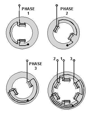
Three-phase induction motors have three coils, placed 120 electrical degrees apart from each other, which form the stator winding.
Whereas a rotor is a squirrel-cage type (solid one) and has copper conductors, which are shorted at one end by a circular connecting plate. In a squirrel-cage induction motor is shown.
When voltage is applied to the stator winding, current flows through it, creating a rotating magnetic field. The speed of this rotating magnetic field depends on the number of poles of the stator, and the frequency of supply given to it. This is known as Synchronous speed and is given as:
S =120 f/p
Where S = Synchronous speed in RPM f = Frequency of source in Hz p = Number of poles of stator winding.
The rotating magnetic field induces emf in the rotor by the transformer action. Since the rotor is a closed set of conductors, current flows in the rotor. The rotating fields due to stator currents react with the rotor currents, to produce forces on the rotor conductors and torques.

+++ Squirrel-cage induction motor: Copper bars embedded in End rings,
Iron laminations
This motor is called an induction motor, as it works on the principle of transformer action or induction.
Characteristics of a three-phase induction motor:
- No external starting mechanism is required.
- They come in a variety of horsepower ratings.
- Speed is inherently constant.
- The direction of rotation can be changed easily by reversing any two power lines of the motor.
- Motor runs at a speed lower than the synchronous speed by a factor 'slip'.
- For reduced loads, the power factor becomes poor.
- Multi-speed squirrel-cage motors are available with a provision of changing the number of stator poles by changing external connections.
Speed-torque characteristics of an induction motor
The speed-torque characteristics and torque-slip characteristics of an induction motor are important parameters for determining the performance of the motor. Typical speed- torque characteristic and torque-slip characteristics of a three-phase induction motor.
It can be seen that when a motor starts from zero speed, the start torque is lower than the full load torque and the motor can start at light-to-no load. The normal full load torque is achieved at a point where the rotor speed is only 5% less than the synchronous speed. From this point onwards, the torque drops to zero value since there is no relative motion or slip between the stator and the rotor.
In order to achieve a high starting torque, the rotor is made with high-resistance conductors or else an external resistance is inserted in the rotor circuit.
The nature of the characteristic curve can be changed, in case of a slip-ring type induction motor, by inserting an external resistance in the rotor circuit. If the rotor resistance is increased from r1 to r2, r3, r4 (r1 < r2 < r3 < r4), then the maximum torque remains the same, but the slip at which the maximum torque occurs is shifted. The method of introducing an external resistance in rotor circuit is used, to obtain a higher starting torque, as required, up to the maximum torque limit that the motor can produce. This method of increasing the starting torque can be used only in the case of slip ring or wound rotor induction motors.
++++2 Speed-torque and torque-slip characteristics of an induction motor -- Slip fraction of syn. Speed; Speed % of syn. speed % Torque (full load)
Induction motor startup
The main goals while starting an induction motor are:
- To handle high-starting current
- To achieve high-starting torque
As discussed earlier, rotor resistance determines starting torque. Usually, this rotor resistance is small, giving small starting torque, but good running conditions. So, the squirrel-cage motor can run only with low-starting loads.
If the rotor resistance is increased by some means, then the slip and speed at which maximum torque occurs can be shifted. For that purpose, external resistance can be introduced in the rotor circuit, which is done in the case of slip ring or wound rotor type motors.
When power is applied to a stationary rotor, excessive current will start flowing. This happens due to the fact that there is a transformer action between the stator winding and the rotor winding, and the rotor conductors are short-circuited. This causes heavy current flow through the rotor.
If, for reducing this heavy starting current, starting voltage applied is reduced then it affects the starting torque as well.
To get everything out, the following method of starting is generally used:
- DOL starting
- Auto transformer starting
- Star-delta starting
Induction motor losses and efficiency
The following are the losses in an induction motor:
- Core loss in the stator and the rotor
- Stator and rotor copper losses
- Friction and windage loss
Core loss is due to the main and leakage fluxes. As the voltage is assumed constant, the core loss can also be approximated as a constant. DC can measure the stator resistance. The hysteresis and eddy current loss in the conductors increase the resistance, and the effective resistance is taken at 1.2 times the DC resistance. The rotor copper loss is calculated by subtracting the stator copper loss from the total measured loss or the rotor I^2R loss. The friction and windage loss may be assumed constant, irrespective of the load.
Efficiency = Rotor output/stator input Output = Input Losses -
Example 1:
Consider a three-phase 440 V, 50 Hz, six-pole induction motor. The motor takes 50 kW at 960 rpm for a certain load. Assume stator losses of 1 kW and friction and windage loss of 1.5 kW. To determine the percentage slip, rotor copper loss, rotor output, and efficiency of the motor, perform the following function: Percentage slip The synchronous speed of the motor = (50 × 120) / 6 = 6000/ 6 = 1000 rpm Slip = (Synchronous speed - Actual speed) = 1000 - 960 = 40 rpm Percentage slip = [(40 / 1000) × 100] = 4% = 0.04 Rotor copper loss Rotor input = 50 1 = 49 kW Rotor copper loss = Rotor input × Slip = 49 × 0.04 = 1.96 kW
Rotor output Rotor output = Rotor input Rotor copper loss Friction and Windage loss
= 49 1.96 1.5
= 49 3.46
= 45.54 kW
--
Motor efficiency Motor efficiency = Rotor output/Motor input
= 45.54 / 50 = 0.9108
= 91.08%
Principle and operation of a three-phase synchronous motor
The three-phase synchronous motor is considered as a constant-speed motor with large size and high ratings. As the name suggests, it runs from no load to full load at the same speed. As we have seen in an induction motor, there is a slip. However, here the motor runs at the same speed as that of the rotating magnetic field.
The construction of a synchronous motor is similar to that of an alternator. The stator winding is connected to the three-phase supply and the rotor has a DC field winding. When three-phase voltage is supplied to the stator winding, this produces a rotating magnetic field. The torque .produced on the rotor is in a direction which will make the rotor field align with that of the stator. In a stationary rotor the torque is first in one direction and then the direction reverses depending on the relative positions of the stator's rotating magnetic field and the rotor's magnetic field. Due to the inertia of the rotor, it won’t move in any direction. That is why synchronous motors are not self starting. Now, if it’s made to run at some speed, then gradually, the stator and rotor poles of opposite polarity will be locked with each other causing the rotor to run in synchronism with that of the stator's rotating magnetic field. Thus, the rotor will run at a synchronous speed.
To make this happen, a synchronous motor is made to run like a normal induction motor at first, and then, like a synchronous motor.
For that purpose, the rotor has two windings, one is the AC winding, like a squirrel cage winding or a wound rotor type, and the second is the DC winding. Stator winding is similar to the induction motor.
The three-phase synchronous motor differs from an induction motor, in that the rotor is wound and is connected to a DC source through the slip rings.
The motor starts as a normal induction motor (squirrel-cage/rotor-wound), once the speed of the rotor reaches 90-95% of synchronous speed; then a DC source is applied to the DC winding of the rotor. This in turn, produces the north and south poles in the rotor.
The rotor magnet is now locked on to the rotating magnetic field of the stator and runs at a synchronous speed given by:
Where:
S = Synchronous speed in rpm
f = Frequency of AC source in Hz
P = Number of stator poles per phase.
However, it’s necessary to have an angle between the centerline of the stator pole and the centerline of the rotor pole or field. If the excitation is kept constant, during the operation of the synchronous motor, and the load is increased, it produces a change in the current and in the power factor of the motor. The characteristics of a three-phase synchronous motor are given below:
- • Constant-speed motor
- • Can be used to correct power factor of a three-phase system
- • Is not self-starting
- • Used generally in load applications requiring constant speed with infrequent starts and stops.
++++3 Synchronous motor action -- C/L of stator pole -- C/L of rotor pole
'V' curves
If the armature current of a synchronous motor is plotted against the field current of the motor for a constant mechanical output, the curve produced is known as the V curve.
V curves can be drawn or obtained by tests, for various values of the loads maintained constant during these tests. Typical V curves for a synchronous motor for 'no load', 50% of full load, and full load. If a constant power is delivered, the armature current is reduced and the power factor lags as the field current increases. Then it becomes minimum at unity power factor.
Again, it increases for leading power factor forming a V-shape characteristic.
If the power factor for constant output, is plotted against the field current, the plot will be an inversion of the V curve.
++++4(a) Typical V curves for a synchronous motor -- Armature current, Ia Field current, It, Full load 1/2 load No load Unity p.f.
++++4(b) Power factor v/s excitation -- Lagging -- Leading -- Excitation
Losses and efficiency of a synchronous motor
The following are the types of losses in a synchronous motor:
• Fixed losses include core loss, friction and windage loss, and brush friction loss. These losses can be obtained from a no-load test.
• I^2 R loss in armature windings and stray losses in conductors.
• Excitation circuit losses including field copper loss, rheostat loss, and brush contact losses.
The efficiency of a synchronous motor is determined as follows:
Efficiency ( cos 1.732 Losses)
Hunting of synchronous motors
This is a problem associated with synchronous motors. As the load on the motor increases, the angle between the stator pole and the locked rotor pole gradually increases. The rotor of the motor falls back by a certain angle, behind the poles of the forward rotating field, in order to produce the necessary torque. The stator current will also increase. While the motor speed slows down, it will remain synchronized, unless the load causes synchronization or the locking (of the rotor pole) breaks.
An increase in phase difference causes the motor to draw more current from the mains and increase power flow in the armature. Some of the kinetic energy of the rotating parts is transferred to the load during a speed slow down. The motor cannot decelerate exactly at the required torque angle of the increased load.
It passes beyond this, develops more torque, and increases the speed. This is followed by a reduction in speed and the cycle is repeated. If the load is suddenly thrown off, the rotor poles are pulled into almost opposition to the poles of the forward field, but due to the rotor inertia, the rotor poles travel too far, and are pulled back again. This results in oscillations about the position of equilibrium corresponding to the load conditions on the motor. This periodic change in speed is known as hunting.
The phasor diagram for sudden increase in the load of a synchronous motor.
The armature current increases from Ia to Ia1, Ia2, Ia3, etc., and the torque angle increases from ?, to ?1, ?2, ?3, etc. The excitation voltage (E ) is assumed to be a constant. If the variations in the load are periodic and are synchronized with the natural frequency of the oscillation of the rotor, the amplitude of these oscillations increases cumulatively, and becomes so great, that the motor may fall out of step.
++++5 Current response for different loads with constant excitation for a synchronous motor
Hunting is also known as phase swinging. In order to sort it out, it’s required to damp the oscillations and prevent an increase in the amplitude of swinging. This is achieved by providing a damper winding in the pole shoe of the synchronous motor. When hunting occurs, there is a shift of flux across the faces of the pole shoe, due to the effect of the armature reaction on the field flux. The shifting flux induces circulating currents in the damper winding. The kinetic energy of oscillations is dampened by being converted into heat energy. The induced current opposes the change in the relative positions of the armature flux and the field flux, and thus acts as an effective damper. Thus, this problem of hunting in synchronous motors can be avoided.
Principle and operation of a three-phase wound rotor motor
In addition to a squirrel-cage, a wound-rotor induction motor has a series of coils set into the rotor. These are connected through the slip rings to external variable resistors.
The three-phase rotor connections are then brought up to slip rings. It’s now possible to vary the rotor resistance, by introducing a different resistance in the rotor circuit through the slip rings provided. The speed and the starting torque will vary. The stator winding is similar to an induction motor with an individual three-phase winding placed 120° electrically apart.
A wound-rotor induction motor is shown. It works as a normal induction motor with a three-phase supply given to stator windings. The only difference is that the speed varies depending on the rotor resistance.
High-starting torque is obtained with a low-starting current. When no resistance is introduced, the motor will run at full speed. As resistance is increased in the rotor circuit, the speed will reduce. For normal running, the slip rings are short-circuited.
++++6 Wound-rotor induction motor -- Starter; Run Start Mains supply Rotor Winding Stator Slip rings
Wound-rotor motor startup
For a high-starting torque, the motor is started with the rotor circuit starter resistance in the circuit.
As the motor gains speed, the rotor resistance is reduced gradually. This will shift the synchronous speed and maximize the torque curve from the wound-rotor motor to an induction motor curve. Finally, the rotor or slip rings will be short-circuited.
For some motors, the rotor resistance is introduced in small steps.
Merely interchanging the two supply voltage leads can change the direction of the motor.
The following are the characteristics of a three-phase wound-rotor motor:
- • Achieve high-starting torque with low-starting current
- • Generally used in applications where on load starting is required
- • Is self-starting
- • Speed adjustment is possible up to a good extent
- • Speed varies a lot when used with the rotor resistance
The high starting torque of the wound rotor motor and the capability to control the speed by varying the resistance has made this form of motor popular for lifting applications such as hoists and cranes. Also, the relatively lower starting current and the high torque makes it a popular choice for large capacity drives on weak electrical systems and for high inertia loads such as rotary kilns and blowers.
Fundamental of single-phase AC motors
Types of single-phase AC motors
Single-phase AC motors are also very widely used in industrial, commercial, as well as residential usage.
The main types of AC single-phase motors are:
- • Induction motors
- • Universal motors
- • Synchronous motors
Most of the single-phase AC motors are induction motors with different arrangements for starting.
Induction motor
In the previous section, we have seen how the three-phase supply sets up a rotating magnetic field that can start the motor. The induction motor, however, is a single-phase motor. Problems are avoided by introducing a second phase artificially to produce a rotating magnetic field for starting.
A schematic diagram of a two-pole single-phase induction motor. The alternating current is supplied to the stator winding, the stator field axis remains fixed along with the main axis, joined at the centers of the two poles, alternating in polarity and varying sinusoidally.
AC field; Squirrel-cage rotor; Stator
++++7 -- A single-phase induction motor with two poles
It can be shown mathematically that a pulsating magnetic field can be resolved into two equal rotating magnetic fields revolving in opposite directions, each trying to drag the rotor with it. Therefore the rotor remains stationary. However once the rotor starts rotating in any direction, the torque developed in that direction becomes higher and the motor continues to pick up speed till it reaches its rated speed. Thus a single phase induction motor is not self starting but requires some external means of initiating rotation.
This is done by having two stator windings. In addition, to produce a phase difference between two windings currents, a capacitor or an inductance is introduced in the starter winding circuit. Once the motor reaches a normal speed, the starting winding is switched shut.
Once the motor starts, it will continue to run in the direction it has started. To reverse the direction of the motor any one of the winding leads has to be reversed.
Characteristics of single-phase induction motor:
- • Works on a single-phase supply
- • Auxiliary means of starting is required
- • Are larger for the same horsepower compared with a three-phase motor
- • Torque produced by motor is pulsating and irregular
- • Mostly used in domestic and residential application
Types of single-phase induction motors
Split-phase induction motor
This is a single-phase split in two-phase currents for creating a two-phase condition. Thus, phase splitting creates a rotating field. In the split-phase motor, an auxiliary winding in the stator is used for starting, with either a resistance connected in series with the auxiliary winding, known as the resistance start, or a reactor in series with the main winding, known as the reactor start.
The start winding of a split motor is made up of a few turns of a small diameter wire giving a high resistance and a low reactance.
They are used in small machines that require low torque.
Capacitor-start induction motor
A single-phase induction motor with only a squirrel-cage rotor has no starting torque.
In this motor, a capacitor of suitable size is introduced in the starting winding circuit and a phase difference is created between the two windings.
In the capacitor-start single-phase motor, an auxiliary winding in the stator is connected in series with a capacitor and a centrifugal switch. During the starting and the accelerating period, the motor operates as a two-phase induction motor. At about 67% of the full load speed, the switch disconnects the auxiliary circuit and the motor thereafter runs as a single-phase induction motor.
Single-value capacitor or capacitor split-phase motor
In a single-value capacitor, or a capacitor split-phase motor, a relatively small, continuously rated capacitor is permanently connected in one of the two-stator windings. This ensures that the motor starts and runs like a two-phase motor. The capacitor and the winding must be continuously rated. These motors are generally used for small pumps or such similar applications.
Capacitor-start /capacitor-run motor
In the capacitor-start, capacitor-run motor, the starting or the auxiliary winding remains connected in the circuit during running.
In order to have a high-starting torque, the capacitor rating should be high, but during running, a small value capacitor is suitable.
To solve this issue, two capacitors of different ratings are used. One is known as the starting capacitor and the other, as the running capacitor.
The starting capacitor is switched out of circuit once the motor reaches full speed.
These motors have good starting torque and a quiet running.
Shaded-pole induction motor
This is another method to create two phases, with phase differences using pole shading.
The shaded pole has salient poles, each pole split into two sections. A small part of each pole face is wound with a short-circuited copper ring. When supply is given, the flux under the shaded portion lags behind that of the unshaded portion. Thus a phase difference is created. This causes the creation of a rotating magnetic field.
The shaded pole motor is inexpensive, since it does not consist of an auxiliary winding or other mechanisms. These are low-torque motors, generally used for small fans and blowers.
Repulsion-start single-phase motor
The principle of operation of the repulsion-type single-phase motor is an interesting contrast with other motors.
In a repulsion-start single-phase motor, a drum-wound rotor is used, which is similar to a squirrel-cage rotor. The circuit is connected to a commutator with a pair of short-circuited brushes. These are set such that, the magnetic axis of the rotor winding is inclined to the magnetic axis of the stator winding. The current flowing in the rotor circuit reacts with the field, to produce a starting and an accelerating torque. At about 67% of the full load speed, the brushes are lifted, the commutator is short-circuited and the motor runs as a single-phase squirrel-cage motor.
The repulsion induction motor employs a repulsion winding on the rotor during the start and running. The repulsion induction motor has an inner squirrel-cage winding and an outer winding on the rotor, which acts as a repulsion winding. As the motor speeds up, the induced rotor current partially shifts, from the repulsion winding to the squirrel-cage winding and the motor runs partly as an induction motor.
Repulsion-start motors have a high-starting torque. Changing the position of the brushes can vary their speed.
Series-wound single-phase or universal motor
The series-wound single-phase motor, has a rotor winding in series with the stator winding, similar to the series-wound DC motor.
This is similar to a DC series motor with a similar high-starting torque. This motor is also called the universal motor because it’s designed to operate on either AC or DC supply.
When an AC is applied, there is an instantaneous change in the field and armature polarities. Since the field winding has a low inductance, it creates reversals in the current direction at the proper timings.
As the motor can also be operated on direct current (DC), it’s also known as the universal motor.
Single-phase synchronous motor
This is similar to a three-phase synchronous motor in terms of speed, as this also runs at a constant speed. The stator winding is connected to a single-phase supply, while the rotor is made up of a permanent magnetic material.
The resistor and the capacitor are connected in series with one winding. This results in a 90° phase shift between the two windings.
For the first 90°, one set of the windings produces a force that attracts the electromagnet rotor. The second set of phase windings again attracts a new position. This provides the rotor, the force required to start and continue running.