AMAZON multi-meters discounts AMAZON oscilloscope discounts
.
1 Introduction
Lightning is one of the most widely studied and documented natural phenomena. It’s also one of the main causes of transient over-voltages in electrical systems. A proper understanding of lightning is essential for planning protection against lightning strikes so that no untoward damage is caused to buildings and electrical installations.
A lot of research has been done over a number of years worldwide and several publications as well as national and international standards have evolved which give us a good insight into this phenomenon. Some of these are:
• AS 1768: 1991 Australian standard on lightning protection
• ANSI/NFPA 780 National lightning protection code
• IEEE 142: 1991 IEEE green guide ( Section 3)
• IEC 1024:1993 Protection of structures against lightning.
Lightning is the sudden draining of charge built up in low-cloud systems. It may involve another cloud system (which is not of much interest to us in this guide) or ground (which is). The flow of charge creates a steep fronted current waveform lasting for several tens of microseconds. The flow is more usually that of negative charges though at times it may involve positive charge flow too. The latter are generally of lower magnitude and hence not critical to this discussion. FIG. 1 shows a typical lightning waveform.
Some of the parameters of interest to us are:
• Peak current I usually expressed in kiloamperes
• Rate of rise of current dI/dT in kiloamperes per microsecond
• Time to crest TCR in microseconds
• Time to fall to half of peak value TH. As the rate of rise is not uniform throughout, this value is further expressed as dI/dT (Max), dI/dT (10/90%) and dI/dT (30/90%). dI/dT (Max) is the maximum value of slope in the rise curve, dI/dT (10/90%) is the average slope between 10% of peak current and 90% of peak current and so on.
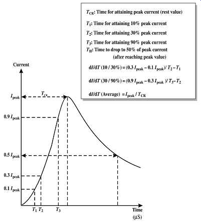
FIG. 1 Typical waveform of lightning
The occurrence of lightning flash starts with a buildup of charge in a cloud system close to the ground. This charge is usually of the order of several million volts and usually of negative polarity at the bottom. Though the exact mechanism of charge separation is not clear, observations indicate that the ice particles in the top portion of the cloud are positively charged whereas the heavier water particles in the bottom portion of the cloud carry a negative charge. FIG. 2 shows the charge separation in a cloud and the corresponding induced charges in the ground. The movement of clouds causes corresponding movement of positive charges on the ground. This is observable as current flow in metallic pathways such as pipelines on the ground.
The high electrical field causes ionization of air and creates a conducting path. This usually happens near the cloud and the ionized path is called the downward leader. The leader precedes in steps of 20-30 m toward the ground, each step forming further ionization of the subsequent step. Simultaneously, from the high points or structures on the ground upward leaders of positive charges start forming. The interception of downward leaders and upward leaders completes the conducting path between the cloud and the ground and results in a lightning strike (see FIG. 3). The lightning flash along the ionized path causes a very high peak of current amounting to several kilo amperes and dissipates its energy in the form of heat (temperatures up to 20 000°C for a few microseconds), sound and electromagnetic waves (light, magnetic fields and radio waves).
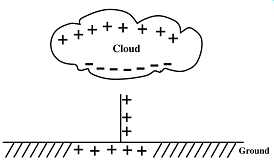
FIG. 2 Charge separation in a cloud and induced charges in the ground

FIG. 3 Lightning strike initiation
Each lightning strike consists of several component parts (each is a current wave called a stroke). The first current wave with a relatively lower dI/dT rate but higher in magnitude and several more (on an average 3) of much higher dI/dT but lower peak currents. FIG. 4 shows a typical lightning discharge.
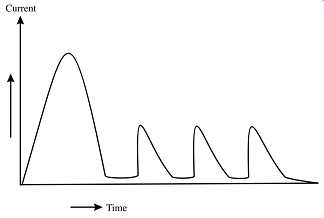
FIG. 4 A typical lightning discharge with multiple wave components (strokes)
Like any typical natural phenomena, lightning strikes are not all identical but vary widely in their parameters. The values of these parameters are therefore defined in a probabilistic format. The tables shown in FIGs. 5 and 6 are examples of such variation. FIG. 5 shows a table for peak lightning current. FIG. 6 shows the maximum and average rate of rise of lightning current.
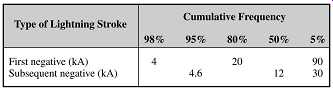
FIG. 5 Peak lightning current values
2 Incidence of lightning
Lightning depends on both atmospheric and geographical factors. It’s usually associated with areas having convection rainfall. It requires presence of high moisture levels in air and high surface temperatures on ground. For example, the incidence of lightning is very high in Florida whereas in colder locations such as Canada where moisture levels in atmosphere are equally high are much less prone to lightning. Since the protection to be given to buildings is a function of the probability of lightning strikes, the frequency of lightning occurrence has been extensively studied and the results are published in the form of annual isokeraunic maps for different world regions. These are contour maps, which show the mean annual thunderstorm days of the region involved.
A thunderstorm day for this purpose is defined as one when thunder is heard at the point where it’s measured. This obviously cannot indicate whether it’s a result of inter-cloud or cloud to ground discharge. It does also show the frequency/number of instances or severity of cloud to ground strikes. Further studies are under way to gather such data and may result in modifications to the present methods of lightning risk assessment.
The isokeraunic map for Australia and New Zealand as well as Continental USA and Canada are shown in FIGs. 7a-e.
FIG. 6 Maximum and average rate of rise of lightning current
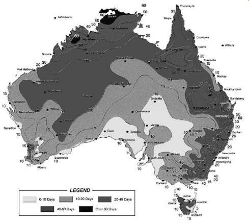
FIG. 7a Isokeraunic map of Australia
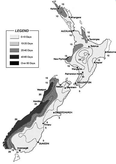
FIG. 7b Isokeraunic map of New Zealand
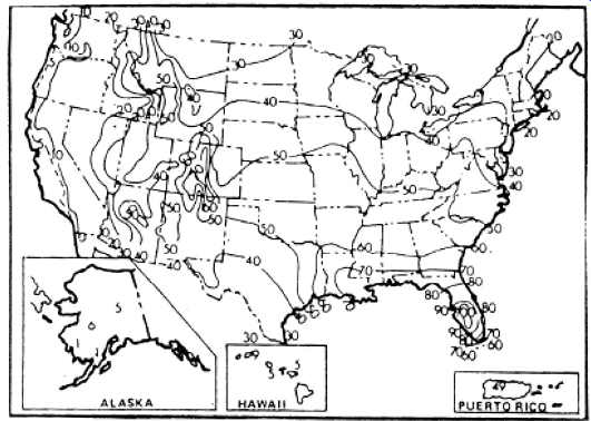
FIG. 7c Isokeraunic map of USA
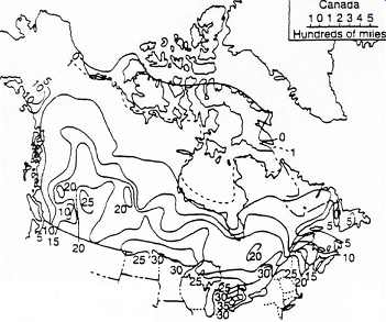
FIG. 7d Isokeraunic map of Canada
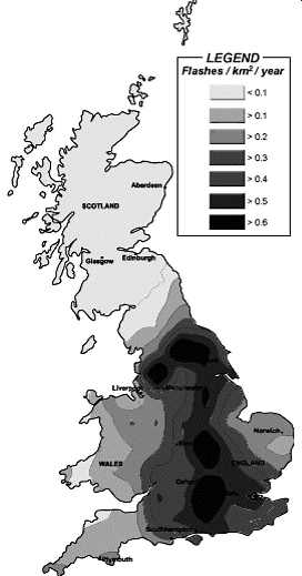
FIG. 7e Isokeraunic map of the UK
Methods have been developed to compute the ground flash density (flashes/ km^2 /year) from the average thunderstorm days. Table in FIG. 8 gives the relationship between these parameters.
3 Probability of lightning strike
The probability of lightning strike depends on two factors: the incidence of lightning strikes in the geographical area where the structure is situated and the attractive area offered by the structure for lightning. The attractive area can be defined as the horizontal area within which a downward leader will be intercepted by an upward leader originating from the structure. FIG. 9 shows the attractive area for a lightning mast. The attractive area in turn depends on the attractive radius RA (shown in FIG. 9). If the downward leader of a lightning comes anywhere within the sphere formed by the attractive radius with the top of the mast as center it will strike the mast.
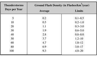
FIG. 8 Relationship between thunderstorm days and ground f lash density
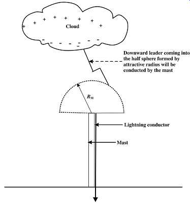
FIG. 9 Attractive radius of a lightning mast An empirical formula for
the attractive radius is:
0.6 0.74 A 0.84 R hI =××
Where RA is the attractive radius in meters, h is the height of the lighting mast in meters and I is the peak lightning current in kiloamperes.
For a horizontal conductor (such as the shield wire provided on an overhead electrical line) the attractive distance LA is given by the formula:
0.6 0.74 A 0.67 LhI =××
Where LA
... is the distance of attraction on either side of the conductor in meters, h is the height of the conductor from ground in meters and I is the peak current of lightning in kiloamperes.
The number of lightning strikes that a structure will attract in 1 year can be arrived by multiplying the ground flash density (in flashes/km^2 /year) with the attractive area expressed in km^2.
4 Method of lightning protection
Lightning protection to any building or structure consists of providing a safe low impedance conducting path for flow of lightning discharge currents to ground without allowing them to flow through the building structures. In practical terms, such protection consists of an air termination, down conductors and ground electrodes. A lightning mast independent of the structure but near enough to divert any lightning occurring in the vicinity is one example of protection. FIG. 10 illustrates how a nearby mast protects a building. The protection offered may not be complete if the attractive radius of the building to lightning extends well beyond that of the mast. In such a case, it’s possible that some of the strikes may hit the building rather than the mast.
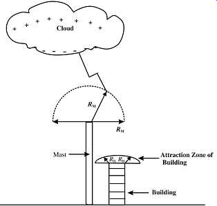
FIG. 10 Building protected by a nearby mast
Whether a structure gets adequate protection from a lightning mast can be verified by using the principle of cone of protection. FIG. 11 illustrates this principle. The angle A can vary between 30 and 60 º depending on the degree of lightning protection desired for the structure (lower values for higher degree of protection).
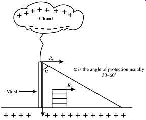
FIG. 11 Example of the cone of protection principle
This concept is somewhat outdated and other better methods have been evolved to more accurately predict the protection offered. One such method is the rolling sphere principle of protection. FIG. 12 illustrates the protection offered by a building's lightning protection system to adjacent structures.
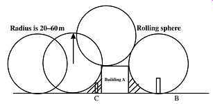
FIG. 12 Rolling sphere method of protection
A sphere is rolled over the protecting structure and the shaded areas which the sphere cannot touch are within the protection zone. The radius of the sphere can vary between 20 and 60 m depending on the degree of protection required. The standard protection will consider a radius of 45 m and increased degree of protection can be obtained by reduction of the radius (refer FIG. 13).
===
Protection Level -- Radius of Sphere (m)
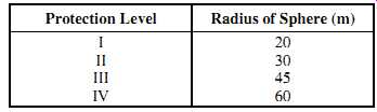
FIG. 13 Rolling sphere radius for different protection levels
===
Protection levels shown in FIG. 13 are in descending order of importance of the structure to be covered (protection level I to be applied for structures requiring the greatest protection, and so on). Since all buildings cannot be protected by a free standing mast, the more usual approach is to have the conductors placed on the building itself (called as air terminations) and connect them to the ground through down conductors. The air terminations can optionally be vertical spikes placed on the top periphery of the building. These air terminations can be connected by a flat conductor run on the roof thereby offering multiple paths for the lightning current to flow to ground. The down conductors are connected to dedicated ground electrodes to offer a short conducting path to ground. FIG. 14 illustrates this arrangement.
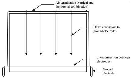
FIG. 14 Typical lightning protection to a building
Lightning behaves like a current source. In other words, the flow of current is independent of the circuit impedance. If the current path to ground has high-impedance elements, the lightning current, which is of the order of several kiloamperes as we saw earlier, produces a very high voltage drop. This voltage appearing on the conducting elements can cause secondary flash to nearby earthed objects. It can also cause damage to building structures by forcing a path through non-conducting building elements. This explains why the lightning conductors should be of as low impedance or in other words as low a length as possible. FIG. 15 illustrates the example of side flashes.
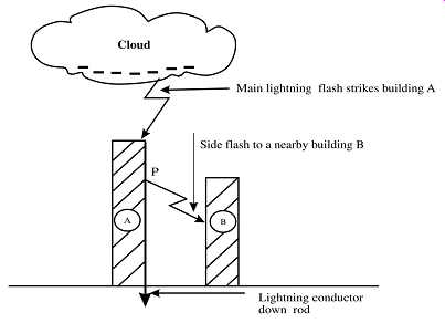
FIG. 15 How side flashes are caused
5 Planning for lightning protection
The protection to be given for a structure or facility against lightning strikes is based on the probability of lightning strike (as detailed in the previous section) and the extent of risk of damage or disruption that a lightning strike can cause. Based on the latter criterion, structures can be divided into various classes in ascending order of protection requirement.
Class 1: Structures, which need very little or no additional protection except connecting them to an effective ground electrode, come under this category. These are all-metal structures, buildings with metallic roofing, side cladding and metallic frame work, stand-alone metallic masts, etc.
Class 2: Structures that have a metallic roof, side cladding and non-conductive framework are in this category. Protection to these structures is provided by down conductors bonded to the roof and side members and connected to ground electrodes.
Class 3: These include metallic frame buildings with non-metallic roof and side cladding. In this case, air terminations on the top of the building and on other non-conducting surfaces connected to the metal frame of the building are required to protect the insulating surfaces from being punctured by lightning.
Class 4: This class includes completely non-metallic structures such as buildings and tall chimneys/stacks constructed of reinforced concrete or masonry. These structures need extensive protection using air terminations, down conductors and grounding electrodes.
An example of such protection is shown in FIG. 16.
FIG. 16 Example of lightning protection of a class 4 structure
Class 5: Buildings of historic or public importance or those containing valuable materials, places where a large number of people can gather at a time and public utilities such as power plants, water works, etc. come in this category and need utmost attention while planning protection.
6 Improvements to lightning protection
The protection to buildings and structures can be improved by better methods of prediction and by the use of active protection systems. We will cover them briefly below.
In 1979, Eriksson presented an improved model, which allows for the intensification of ambient electric field created by a grounded structure. Eriksson's work was a fundamental step forward in lightning protection design, since it supported the field observations that the majority of lightning flashes terminate on the corners and nearby edges and other sharp features of unprotected structures, i.e. the points of highest electric field intensification. The ERICO scientists and engineers extended Eriksson's basic model for application to practical structures back in the late 1980s. This has been done through computer modeling of electric fields around a wide range of 3D structures and by application of the concept of 'competing features' to determine whether a structure is protected. This relatively new method has been known worldwide as the collection volume method (CVM) (refer to FIG. 17).
FIG. 17 Collection volume method
The CVM takes the physical criteria for air breakdown, together with a knowledge of the electric field intensification created by different points on a structure and uses this information to provide the optimum lightning protection system for a structure, i.e. the most efficient protection design for the required protection level. Using the modern risk management approach, the CVM output depends on user-selected protection levels as per the previous rolling sphere method.
Active protection systems are also being offered by several vendors and are claimed to offer a higher degree of protection compared to the passive systems comprising air terminations and down-comers described earlier. The efficacy of many of these systems is however to be proven under actual installation conditions. The basic principle behind these systems is as follows. The active air terminations provided in these systems (which are vertical rods with an active component at their tip) generate a high electrical field as soon as a downward leader from a cloud starts toward the ground and immediately cause an upward leader to emanate from the air termination. Though a normal air termination also behaves in roughly the same fashion, the active protection systems react much faster. As a result the upward leader from the active air termination reaches out much higher resulting in the lightning strike to be invariably directed to the ground through the protection system.
7 Factors governing decision whether or not to protect
Standard AS 1768 provides clear guidelines to take a decision to provide or not to provide lightning protection to a building or structure based on an assessment of risk involved.
The assessment is done in terms of the likelihood of the structure being struck and the consequences of any such strike. The use of the structure, the nature of its construction, the value of the contents and the prevalence of thunderstorms in the area can all be considered in making the assessment.
A decision to provide lightning protection may, however, be taken without any risk assessment, For example, where there is a desire that there should be no risk to a structure at all.
Examples of such structures are:
- • Those in or near which large numbers of persons congregate
- • Those concerned with the maintenance of essential public services
- • Those in areas where lightning is prevalent
- • Very tall or isolated structures and
- • Structures of historic or cultural importance.
Where it’s thought that the consequential effects will be small and that the effect of a lightning flash will most probably be merely slight damage to the structure, it may be economic not to incur the cost of protection but to accept the risk. Even then, it’s better to make an assessment so as to give some idea of the magnitude of the risk that is being taken.
The need to protect electronic equipment and to protect persons against potential differences associated with metallic services increases with the building area. In such cases even though the construction of the structure does not warrant protection, appropriate measures must be taken to avoid risk to persons and equipment.
The standard also stipulates that any structure which is entirely within a zone protected by an adjacent object or objects (whether protected or not) should be deemed to be protected, that is no separate protection is necessary for such structures.
The standard defines a set of five indices:
- 1. Index A type of structure
- 2. Index B type of construction
- 3. Index C height of structure
- 4. Index D situation (location)
- 5. Index E lightning prevalence (thunderstorm days/year).
The sum of these indices (R) can be used to determine the need for protection. For more details, the relevant standard may be referred.
8 Effect of lightning strike on electrical lines
The foregoing discussion concentrated on the principles of lightning strikes and how their effects can be mitigated. However, lightning strikes on electrical lines or substations are those that cause problems in the distribution network which come right into our residences and offices. A full discussion on the protection of transmission and distribution lines from direct lightning strikes is beyond the scope of this guide. We will, however, briefly touch upon this aspect further.
A direct strike on a conductor of a power line causes extremely high voltage pulses at the strike point, which are propagated as traveling waves in either direction from the point of strike. The crest of the pulse can be calculated as:
= VI Z ×
Where V is the crest voltage, I is the peak lightning current and Z is the impedance seen by the pulse along the direction of travel.
Impedance Z is equal to half the surge impedance of the line when struck at mid-point and can be approximately as much as 150 ohm. Thus for a peak current of 40 kA, the voltage of the pulse can be as high as 6000 kV. Since the basic insulation level of most systems is much lower than this value, it’s clear that such a pulse will cause failure of insulating components along the line. It’s therefore necessary that no direct strike must be permitted on the overhead power line's phase conductors. This is achieved by stringing one or more shield wires along the phase conductors sufficiently above them so that the shield wires attract direct strikes and not the phase conductors. The shield wire is earthed at each transmission tower and thus the lightning current safely passes into the groundmass.
The clearance between the phase conductors and the shield wire must be selected so that air space between them does not breakdown by the high impulse voltage generated in the shield wires. This is easily achievable in systems of 66 kV and higher.
Even when protected in the above manner, the flow of the pulse of lightning current in the shield wire causes an induced voltage pulse in the phase conductors. These being much smaller in value than the direct pulse safely pass along the line without causing any insulation failure. To protect the equipment at the termination point of the overhead lines (such as circuit breakers, transformers, measuring devices, etc.), lightning arrestors are provided at the point of termination. These arrestors absorb any surges in the line and prevent them from traveling into the substation equipment.
These arrestors are essentially non-linear resistors in a porcelain housing which at normal voltages present a very high resistance. They are designed to break down at voltages above the highest system operating voltage (but lower than the basic insulation level of the system) thereby becoming good conductors and pass the energy of the lightning impulse to the ground. Once the voltage comes down (after the discharge of the pulse is over) the arrestors return to their original high-impedance state. The arrestors are placed on structures and their line terminals connected to each phase of the line. The other end of the arrestor (ground terminal) is connected to the substation grounding system through short ground conductors of adequate cross-sectional area. Arrestors can also be optionally provided with surge counters for the purpose of monitoring their action.
9 Summary
In this section, we have reviewed the phenomenon of lightning, their effects on the installations in the ground. The probability of lightning strikes based on the ground geography and the configuration of the grounding installation was analyzed. We also went through the methods adopted for safeguarding the installations from the effects of a strike. The various classes of structures and how these are to be protected were also covered. The effect of lightning on electrical installations and the practices for ensuring their safety were also described.