AMAZON multi-meters discounts AMAZON oscilloscope discounts
The amplifiers for these valves use op amp circuits to provide variable-voltage or variable-current outputs. The circuits also provide ramp-up and ramp-down capabilities by adding a capacitor and a potentiometer to the circuit. The potentiometer is adjusted to increase or decrease the time constant with the capacitor, which increases or decreases the ramp time. The arrangement of the capacitor and potentiometer makes this op amp an integrator.
Ill. 1 shows the capacitor and potentiometer connected to the op amp integrator to provide this ramp-type signal. The ramp-up signal is needed to ensure the valve is opened smoothly when voltage is first applied and that the machine motion caused by the valve is also smooth. If you are a technician, you may be expected to locate the potentiometer on the amplifier board and adjust it to match the ramp-up and ramp-down signals so that the machine motion is smooth as the valve opens and closes.
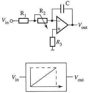
Above: Ill. 1 Typical op amp circuit for a proportional valve. The
potentiometer and capacitor provide a time constant that controls the
slope of the ramp-up and ramp-down signal.
Ill. 2 shows an example of a ramp-up signal and a ramp-down signal that are compared to the on-off signal received by the amplifier. When the on-signal is energized to the valve amplifier, it's shown as instantly going from off to on. The amplifier produces the ramp signal and the slope of this signal is determined by the value of the potentiometer and capacitor which cause the time constant. It's important to remember that one can only adjust the potentiometer, since the capacitor is a fixed capacitor. The opening of the valve will be gradual, which will make the machine operation very smooth. When the signal to the valve amplifier is de-energized, the ramp-down signal will gradually close the valve, which will again make the machine operation very smooth. If the machine motion is too jerky or too rough, one will need to adjust the slope until the machine operates smoothly. One may have to readjust the slope periodically as the machine wears.
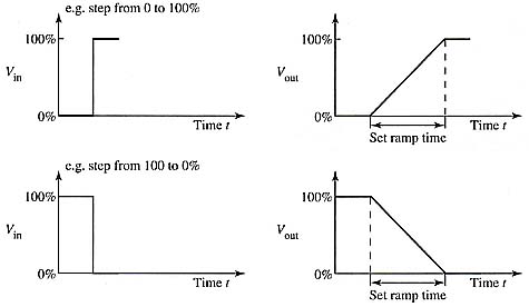
Above: Ill. 2: Typical ramp-up and ramp-down signals. The slope of
the ramp is controlled by the capacitor and potentiometer. The ramp provides
smooth operation of a machine when hydraulic power is applied and turned
off.
Ill. 3 shows a picture of a typical valve amplifier, and Ill. 4 shows the electrical schematic diagram of this amplifier. The supply voltage for the amplifier is 24 V dc and t is connected to terminal 24ac and 18ac. Terminal 24ac is the positive terminal.
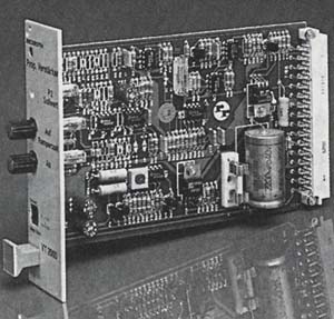
Above: Ill. 3: Amplifier card for proportional valve. This card slides
into a card cage and receives an input signal (0-9 volts dc) from a PLC
(programmable logic controller) and sends an output signal (0-6 volts
dc) to a proportional valve.
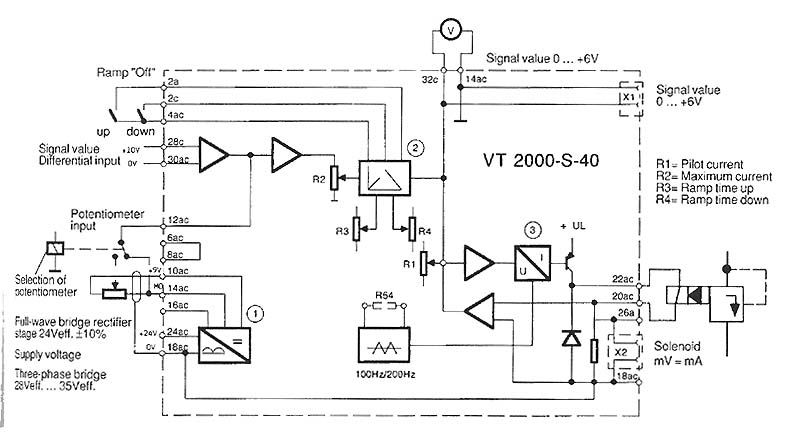
Above: Ill. 4: Electrical schematic of a typical amplifier circuit.
The amplifier receives its power supply and input signal on the left
side of the circuit, and the proportional valve is connected to the right
side of the circuit.
The circuit in box 1 is a rectifier, filter, and regulator that ensures the dc voltage is pure and without ripple. The output of this circuit is +/-9 V dc, and it can be adjusted to +/- 0.1 volt with the potentiometer that's connected to terminals l0ac and 14ac. The +9 V dc is measured between terminals 10ac and 14ac, and the -9 V dc is measured between terminals 16ac and 14ac. Terminal 14ac is considered the 0 V terminal.
An external analog signal is connected to the amplifier card at terminals 28c and 30ac. The 28c terminal is the plus terminal and the 30ac is the negative terminal. The analog signal voltage should be 0-10 V dc. This signal would typically come from a controller such as a programmable controller or other microprocessor controller that has machine control logic.
The proportional valve is connected to the output terminals of the amplifier on the right side of the diagram. These terminals are marked 22ac and 20ac. The output will be a variable voltage (0-6 volts) with a corresponding variable current (0-800 mA). A voltmeter can be connected to terminals 32c and 14c to provide a panel meter that indicates the status of the valve signal. This small voltmeter is usually mounted near the operator panel or near the valve to give a visual indication of the voltage signal that's being sent to the valve.
The circuit in box 2 is the ramp-up and ramp-down circuit. A switch is connected across terminals 2a and 4ac to activate the ramp-up option, and a switch is connected across terminals 2c and 4ac to activate the ramp-down option. If these switches are not closed, the ramps are not activated.
The circuit in box 3 is the output stage of the amplifier. This circuit utilizes a pulse-width modulation (PWM) circuit. The current is pulsed to conserve energy and minimize the thermal load to the amplifier.
Four potentiometers are identified to provide adjustment for pilot current (R2), maximum current (R2), ramp-up time (R3), and ramp-down time (R4). These potentiometers allow the technician to adjust the amplifier to customize the valve action to the machine's action. At times two similar machines will react slightly differently when the same amount of hydraulic pressure is used to cause machine movement. These differences can be adjusted from machine to machine through the potentiometer so that the machine operation will be as smooth as possible.