AMAZON multi-meters discounts AMAZON oscilloscope discounts
The solenoids discussed so far are all used as outputs for both electronic and electromechanical circuits. You may be familiar with electronic circuits that use a triac in an optocoupler to energize solenoid-type output. Other electronic circuits may use amplifiers or transistors to energize solenoids. Ill. 1 shows an example of a circuit that uses a triac in an optocoupler. In this application of a high-speed weighing system solenoids are used to energize a pneumatic ejector system. The solenoids are connected to a terminal board to make troubleshooting easier.
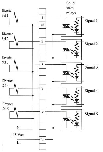
Above: Ill. 1: AC powered solenoid coils controlled by a triac in an
opto-coupler. The solenoids are on the left side of the terminal strip
in this diagram.
The ejectors use a small pneumatic cylinder that can extend and retract extremely fast. When an overweight product is detected, the solenoid is energized and the cylinder is extended to push the product off the conveyor and retract to be ready to repeat the operation in less than 0.1 second. This allows the system to weigh 600 products per minute. Since the weighing system is all electronic, electronic circuits may use triacs or transistors to energize and de-energize the solenoid valve. If transistors are used, the solenoid coils will be powered by DC voltage, and a diode must be connected in reverse bias across the coil terminals to protect the circuit against the reverse polarity of inductive voltage that occurs when the solenoid is de-energized.
Ill. 2 shows a solenoid coil controlled by a motor control circuit that uses a selector switch and timer. In this type of application a small carrier is used to hold an automobile dashboard while a plastic coating is applied. The plastic coating is a sheet of color film that's draped over the dashboard. When the film is in place, the operator switches the momentary-type selector switch (SS1) to the in position, which energizes the solenoid (SOL1). A set of normally open (NO) contacts from the timer is used to seal in the momentary contacts of the selector switch. When the solenoid energizes, a spool in the solenoid valve moves so air is directed to a pneumatic cylinder that extends and moves the carrier into a baking oven. When the carrier is moved into the oven and the cylinder is fully extended, a limit switch (LS1) is activated, energizing a timer (TMR1). The second set of contacts in limit switch (LS1) and a second set of contacts in the timer (TMR1) also activate the heating element to start the shrinking and curing process. When the timer times out, its normally closed (NC) contacts open and de-energize the solenoid coil. The second set of timer contacts also opens and de-energizes the heating element. The seal in the contacts of the timer (TMR1) also opens so the solenoid coil remains de-energized.
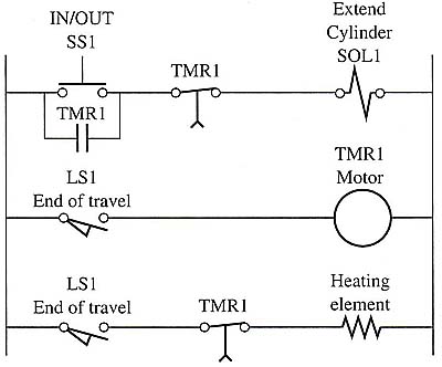
Above: Ill. 2: Electronic ladder logic diagram of selector switch and timer used to control a solenoid valve. The solenoid valve energizes
a pneumatic cylinder that extends an automotive dashboard into a curing
oven for a shrinking and curing process.
When the solenoid coil is de-energized, the spring in the valve causes the spool to return. The cylinder is retracted, causing the carrier to return from the oven so the operator can remove the finished dashboard and place another one on the carrier for the process to repeat.