AMAZON multi-meters discounts AMAZON oscilloscope discounts
Variable DC drives have been used to control DC motors longer than variable frequency drives have been used to control AC motors. The first motor-speed control used DC motors because of the simplicity of controlling the voltage to the armature and field of a DC motor. The main obstacle in using DC motors is the increased level of maintenance involved because the DC motor has brushes and a commutator. Early speed control for DC motors consisted of large resistors that were switched in the motor circuit to reduce the amount of voltage supplied to it. The resistors created problems because of the heat buildup.

above: A PWM (pulse-width modulated) device offers bare-bones features: speed and reversing. The speed is controlled via that rotary "volume" knob. (by Leeson)

above: Leeson's simple DC Controls / SCR Series. You may not need a more-sophisticated DC drive than this.

above: You can skip the drive box (chassis), and just install the drive-circuit guts. This works well for low-voltage DC drives, where circuit-generated heat or space-consuming high-voltage components aren't an issue. (this model by Leeson)
DC drives designed in the 1970s and 1980s combined op amp circuits to provide ramping capability with SCR (silicon controller rectifier) firing circuits to control large voltages. Today, modern DC drives utilize the latest solid-state power-switching technology combined with microprocessors to provide programmable features. When you look at the diagram of a modern DC drive you will notice that much of the circuitry looks similar to an AC drive. The main difference is that the rectifier stage and output stage of the DC drive are combined because the DC drive simply adjusts the DC voltage and current rather than invert it back to AC. Since the output voltage for the drive is DC, SCRs will be used in rectifier circuits. The newest drives have programmable parameters similar to AC drives in that they set the maximum voltage, current, and speed, as well as provide protection against overcurrent, overtemperature, phase loss of incoming power, and field loss.
 The
image on the left shows a typical DC drive as a stand-alone product, and as you would find it when mounted in a panel. From this image you may
notice that's difficult to distinguish a DC drive from an AC drive by
its external physical features. The image below shows a diagram of the
simple DC drive and you can see that the electronic circuits of the drive
are slightly different from the AC drive. In the diagram of the DC drive,
you can see that three-phase supply voltage is provided al the top of
the diagram. This incoming voltage is sent directly to an isolation transformer and then to a three-phase bridge rectifier in the armature power-converter
circuit. The three-phase rectification in the armature power converter
circuit is similar to the rectifier section of the AC drive except large
SCRs are used instead of diodes.
The
image on the left shows a typical DC drive as a stand-alone product, and as you would find it when mounted in a panel. From this image you may
notice that's difficult to distinguish a DC drive from an AC drive by
its external physical features. The image below shows a diagram of the
simple DC drive and you can see that the electronic circuits of the drive
are slightly different from the AC drive. In the diagram of the DC drive,
you can see that three-phase supply voltage is provided al the top of
the diagram. This incoming voltage is sent directly to an isolation transformer and then to a three-phase bridge rectifier in the armature power-converter
circuit. The three-phase rectification in the armature power converter
circuit is similar to the rectifier section of the AC drive except large
SCRs are used instead of diodes.
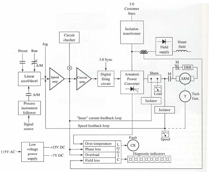
above: Block diagram of
an Allen-Bradley DC drive. Three-phase voltage is supplied at the top
of the diagram, and the DC motor is shown as a shunt field and armature.
The SCRs are used for the rectification section because they can provide voltage control as well as rectification. This simplifies the drive somewhat since rectification and voltage control are combined in one circuit. Op amps provide speed ramps and current ramps for the SCR firing (control) circuit. In the older drives, the op amps were used as stand-alone ramping circuits. In modern drives that have microprocessors, the firing circuits are controlled by digital-to-analog (D/A) circuits that integrate linear circuits with the processor. The voltage from, the armature power converter circuit is sent directly to the armature. The DC motor is shown in this diagram as a shunt field and armature. A tachometer is shown connected to the armature as a dotted line, which means it's physically connected to the motor shaft.
The rectifier section may use six SCRs as a bridge similar to the diode bridge rectifiers in AC drives. Or larger drives may connect two SCRs in parallel for each of the six sections of the bridge to provide a 12 SCR full-wave rectifier circuit. When SCRs are connected in parallel, the current rating of the rectifier is nearly doubled. The firing circuit for the SCRs is synchronized with the three-phase incoming voltage. The firing circuit also receives an input signal called a reference signal or command signal from the speed amp and the current amp. The speed amp receives a feedback signal from a tachometer, and the current amp receives a signal from a current transducer (shunt) that's connected in series with the armature. As the current in the wire to the armature increases or decreases, the voltage across the shunt will increase or decrease and provide a feedback signal to the current amplifier.
In the diagram you can also see that DC field voltage is provided by a smaller diode bridge. The AC voltage supply for this bridge rectifier is tapped off of the output of the isolation transformer prior to the main rectifier in the armature power converter. Since this voltage comes from a diode bridge rectifier, it will be constant Speed control for the DC motor is provided by keeping the shunt-field voltage constant and by varying the armature voltage and current.
Fault circuits are provided in the drive to test for over-temperature, phase loss, overload conditions, and the loss of field current in the motor. Indicator lamps are provided on the front of the drive to show when a fault has occurred. A speed indicator is also provided on the face of the drive to show the actual speed of the motor. The speed indicator receives its signal from the tachometer that's connected to the shaft of the DC motor.
PREVIOUS: AC and DC Drives: Preventive Maintenance | NEXT: DC Drives: Introduction (part 2)