AMAZON multi-meters discounts AMAZON oscilloscope discounts
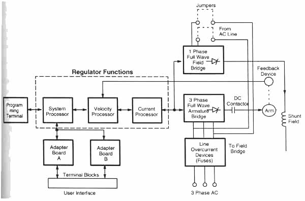
Modern DC drives combine a microprocessor with the drive circuitry, as shown in the diagram on this page. The major difference that the microprocessor provides is that it allows programmable parameters to be used with the drive to set maximum voltages and currents, and provide a variety of ramp-up and ramp-down signals. These parameters are similar to the ones listed for the AC drive presented in the previous section. Another feature the microprocessor provides is closed-loop control such as PID (proportional, integral, and derivative) control. The block diagram below shows of a modern DC drive that incorporates a closed-loop PID control used for speed (velocity) control. A separate control loop for current is also used. In this diagram you can see that three-phase voltage is supplied at the bottom of the drive and is converted to variable DC voltage by the three-phase SCR (also called a thyristor) rectifier section. An encoder is used as the feedback sensor to provide the velocity-feedback signal to the velocity processor. Current sensors can also be used to provide a second loop for current control.

above: Block diagram of
an Allen-Bradley microprocessor-controlled DC drive. This drive provides
PID control of the DC motor speed.
Another feature of the microprocessor controlled drive is that it can be programmed from a programming terminal or programming software that's in a laptop computer. The programming parameters can also be loaded or changed on-the-fly from a PLC. This provides functions similar to those of an AC drive.
HOME | PREVIOUS: DC Drives: Introduction (part 2) | NEXT: DC Drives: An Example