AMAZON multi-meters discounts AMAZON oscilloscope discounts
The pneumatic-assisted control valves require a converter to change the proportional electrical signal to a proportional pneumatic signal. In this figure, the converter is shown as part of the valve. In some cases the converter is a separate part mounted near the valve. The converter is generally mounted in a location where it can be serviced easily and the valve is generally mounted in the piping.
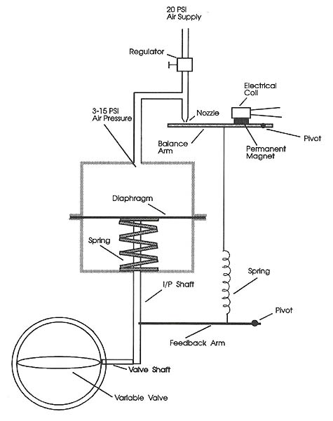
The proportional electrical signal is generally a 4-20 mA current signal, and the air pressure signal is generally set for 3-15 psi. This type of signal converter is called an I/P converter because it changes a current signal (I) to a pressure signal (P). Ill. 1 shows an example of an I/P converter. The operation of this type of I/P converter is similar to the one shown in this figure. It uses a magnetic coil to change the position of a balance beam that controls a small amount of pilot air pressure. The pilot air pressure controls the main air pressure that's regulated at 3-15 psi. The air supply for the I/P converter must be approximately 20 psi so that the converter can control the pressure between 3-15 psi.
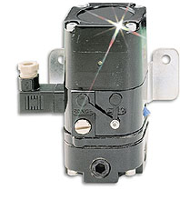
Above: Ill. 1: Current-to-pressure (I/P) converter. This device has
an air pressure gauge to indicate the supply air, and another gauge to
indicate the regulated pressure.
Ill. 2 provides a graph that shows the ratio of current to air pressure. This graph allows one to select a milliamp signal value and determine the amount of air pressure that the I/P converter should produce. For example, when the electrical signal is at its minimum (4 mA), the air pressure signal will also be at its minimum (3 psi). When the electrical signal is at its maximum (20 mA), the air pressure signal will be at its maximum (15 psi). The midpoint value for the electrical signal is 12 mA, which provides 9 psi.
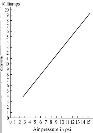
Above: Ill. 2: A graph of the milliamp signal and air pressure signal
for an I/P converter.
The electrical signal for the I/P converter originates from an amplifier. The amplifier receives an input signal from a programmable controller or other type of electronic controller. The signal is generally analog, but it could be a digital signal that's sent through a digital-to-analog (D/A) converter prior to being sent to the amplifier. Many newer microprocessor controlled systems are also capable of providing the analog milliamp signal.