AMAZON multi-meters discounts AMAZON oscilloscope discounts
Before going on to examine the characteristics of the dc motor and dc generator in detail, we will look at how these machines are constructed. The purpose of this section is merely to acquaint you with the important parts of the dc machine and their purpose.
3-1 ARMATURE
Earlier you were introduced to the principles of voltage and torque generation. In the case of voltage generation we saw that a coil had to rotate in a magnetic field. In the case of torque generation we saw that a current had to flow through a coil that was free to rotate in a magnetic filed. In dc machines, the part on which this coil is mounted is called the armature. The rotating part of a machine is also called the rotor. Therefore, when we talk about a dc machine, the armature and rotor both refer to the same part.
The armature is made up of a shaft on which a core of laminated disks is mounted. The disks are made of a steel alloy. The purpose of the laminated disk construction is to reduce a phenomenon called eddy currents. Eddy currents are discussed in Section 4. Figr. 3-1 is a picture of a typical armature. The coil of wire making up the armature winding is wrapped around the armature and embedded into slots. The slots can be seen in Figr. 3-1. Normally, there are several coils mounted on an armature. The way in which these coils are interconnected is discussed in Section 3-6.
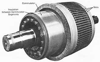
Figr. 3-1 A typical dc motor armature. Note: Insulation between
Commutator Segments.
3-1.1 Commutation
The place at which the interconnection of armature coils is made is called a commutator segment. Commutator segments are conducting strips placed axially on the shaft of the armature. They are electrically insulated from each other and any other metal parts of the armature. It is through the commutator segments that the armature makes contact with the outside world. Current is either taken from the rotating coil (generator action) or received by the rotating coil (motor action) through the commutator.
In Section 2-1 .2 we saw that a conductor rotating in a magnetic field will generate an alternating voltage (shown in Figr. 2-7). Another function of the commutator is to provide internal switching which rectifies the generated alternating voltage to provide a dc output. Figr. 3-2 shows a one-turn coil rotating in a two-pole magnetic field.
As the armature rotates, coil end A is always connected to commutator segment A and coil end B is always connected to commutator segment B. The induced voltage is picked up by two brushes positioned as shown. The brushes are connected to the frame of the generator and don't rotate. As a result of this, the top brush will always be making contact with the coil side in the right half-plane (i.e., passing the north pole) and the bottom brush will always be making contact with the coil side in the left half-plane (i.e., passing the south pole). Rectification has been accomplished since current flow will always be out of the top brush and into the bottom brush. As conductors A and B pass by the top and bottom brushes, respectively, the switching is taking place. The top brush breaks contact with commutator segment A and simultaneously makes contact with commutator segment B. It should be noted here that as the switching is taking place, the voltage being induced in each conductor is zero since at that instant no lines of flux are being cut by the coil.
However, due to an effect called armature reaction (see Section 3-1.3), there will be a small voltage induced. It is the switching of this small voltage which accounts for the sparks seen as you observe a motor or generator in operation. The sparking is caused by the brush momentarily shorting the two commutator segments as the switching takes place. At that instant a current will flow (this is the visible spark) from segment A to segment B through the brush. Ideally, the voltage induced at the point of switching is zero. In this case no sparks would occur since a difference in voltage wouldn't exist between the two segments. However, in a real machine this isn't the case.
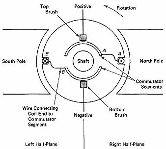
Figr. 3-2 Two-pole generator illustrating commutation.
3-1.2 Brushes
The brushes that are ne for commutation must be good conductors, long wearing, and relatively soft compared to the copper commutating segments against which they are constantly rubbing. For this reason, brushes are made of carbon, graphite, and sometimes a mixture of carbon and copper. After many hours of use, however, brushes will wear down and must be replaced. The brushes are held in place and kept in contact with the commutator segments by brush rigging. The rigging is mounted on but electrically insulated from the machine housing. The rigging includes a spring that forces the brush against the commutator segments to ensure good electrical contact.
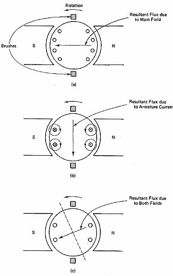
Figr. 3-3 Magnetic fields in a two-pole generator: (a) main field
flux only; (b) armature current flux only; (c) net flux in armature due
to both fields.
3-13 Armature Reaction
If we examine the magnetic fields present in the armature of a dc generator while it's rotating and under load, we would see the simplified picture shown in Figr. 3-3. When a generator is under load, its armature supplies the current to the load. As a result a current exists in the armature winding which increases as the load increases. The current flowing in the armature winding will create a flux of its own which has a circular path around each conductor (see Figr. 3-3b). These small circular paths of flux add up in the armature and form a resultant flux in the downward direction. Since magnetic fields are vector quantities (have magnitude and direction), the two fields add vectorally to form the resultant or net flux shown in Figr. 3-3c. As the conductors rotate, the points at which they are moving parallel to the magnetic field would be where they cross the dashed line in Figr. 3-3c. At this point no lines of flux are being cut and the induced voltage in a conductor is zero. This would be the desired location of the brushes; however, they have been placed in the positions shown in Figr. 3-3. Since the brushes are now out of place, when commutation takes place, sparking will occur.
As you can see from the discussion above, armature reaction makes it look as if the brushes have shifted from their ideal location. For this reason, the phenomenon of armature reaction is also called brush shifting. In addition, as the generator supplies more load, the armature current increases and armature reaction will increase as well.
3-2 INTERPOLES
One way to eliminate or reduce armature reaction is to introduce a magnetic pole between each of the main field poles (see Figr. 3-4). These poles are called inter- poles and are wired so that their polarity opposes the armature current flux shown in Figr. 3-3b. They are wired in series with the armature winding. In this way, as the armature current flux increases due to a rise in armature current, the interpole flux increases proportionately. It should be noted that since the interpoles are wired in series with the armature winding, the total armature circuit resistance would be the sum of the interpole winding resistance and the armature winding resistance.
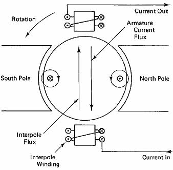
Figr. 3-4 Two-pole machine showing interpole connections.
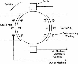
Figr. 3-5 Diagram of a two-pole machine showing compensating
winding connection and location.
3-3 COMPENSATING WINDINGS
Another technique of reducing armature reaction is the use of compensating windings. These windings are set in the pole faces of the main field poles. Their conductors run parallel to the armature conductors as shown in Figr. 3-5. They, too, are wired in series with the armature winding so that an increase in armature current causes an increase in compensating winding flux as well as the armature winding flux. The connection is in such a way that the two fields oppose each other and effectively cancel each other out. Here, again, since the compensating winding is in series with the armature winding, the total armature circuit resistance would be the sum of the resistances of the two windings.
3-4 FIELD POLES
In each of the diagrams in this section representing an armature, the main field flux has been produced by a pair of poles labeled north and south. They are more commonly called the field poles. Field poles are produced in one of two different ways. In small machines, particularly motors used in toys, the field poles are created by a permanent magnet. A permanent magnet is a ferromagnetic material that has been magnetized initially by an external source. This external excitation could be a current flowing in a coil of wire wrapped around the material (see Figr. 1-1), or it could be a strong magnetic field into which the material has been placed. In any event, when the external excitation is removed, the material will remain magnetized due to hysteresis (Section 1-2.1). The magnetism that remains in the material was called residual magnetism in Section 1. The strength of a permanent magnet depends on the strength of the excitation that magnetizes it and the type of material of which it's made. One of the popular materials used for permanent magnets is Alnico (an alloy consisting of aluminum, nickel, cobalt, copper, and iron).
The alternative to a permanent magnet is an electromagnet. It is constructed much as shown in Figr. 1-13. The strength of an electromagnet, although dependent on the size and type of material used, can be easily controlled by the number of turns of wire making up the coil and the amount of current in the coil. It should be noted that unlike a permanent magnet, a source of electricity is needed to maintain the current in the coil. If the current is removed, all that remains will be the residual magnetism, which is small for the type of material used in electromagnets.
When electromagnets are used to produce the field poles, they will generally be one of two types. Either a small current will flow through many turns of thin wire, or a large current will flow through a few turns of a thick wire. In Section 4 we will see why the former is called a shunt field and the latter is called a series field. Figr. 3-6b is a photograph of a typical field pole. We can see from the picture that it's made of laminations (of a steel alloy); in addition, since there are many turns of a thin wire making up the coil, it would be a shunt-field pole.
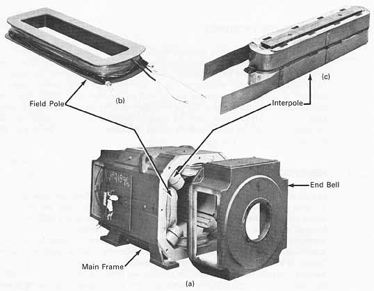
Figr. 3-6 (a) dc motor with end bell removed; (b) shunt field
pole; (c) interpole.
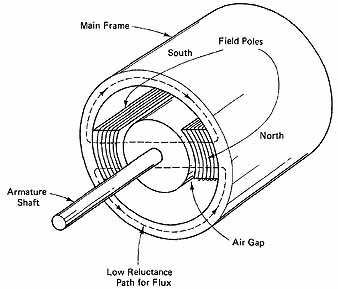
Figr. 3-7 Simplified diagram of a two-pole dc machine.
3-5 MECHANICAL STRUCTURE
Since the armature must rotate freely with very little friction, its shaft is mounted in bearings on both ends. The bearings are mounted in circular plates called end bells at opposite ends of the machine. The end bells fit into a cylindrical steel alloy structure called the main frame. Not only does the main frame support the end bells, armature, brushes, and field poles, but it has another important function. It provides a low- reluctance path for the magnetic flux outside the armature and for this reason is generally thicker than needed for structural support (see Figr. 3-6 and 3-7).
3-6 ARMATURE WINDINGS
The coils on an armature and how they are interconnected are the primary factors determining a dc machine’s characteristics. There are two basic types of windings, the lap winding and the wave winding. In addition, there are several variations of these windings; however, only two will be discussed here.
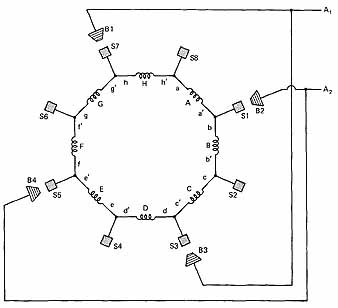
To understand how a lap winding behaves, we will examine Figr. 3-8. The machine shown in Figr. 3-8 has four poles, eight slots, eight commutator segments (Si to S8), and four brushes (B 1 to B4). The diagram shows the end view of the armature, which is rotating counterclockwise. There are eight coils (labeled A to H) wound on the armature, each having N turns. The beginning and end of coil B are labeled b and b’, respectively; the others are labeled similarly. For the instant shown, coils A, C, E, and G are cutting lines of flux and are therefore generating a voltage.
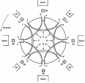
Figr. 3-8 Simplified diagram of an eight-coil armature in a four-pole
machine.
Coils B, D, F, and H are moving parallel to the flux lines and therefore are not generating a voltage. The winding shown in Figr. 3-8, although simplified, will be used to illustrate a lap winding. The difference between a lap and wave winding is in how the coils are interconnected at the commutator segments and the number of segments used.
3-6.1 Simplex Lap Singly Re-entrant Winding
The first thing to notice is that for each coil, when one side is under a north pole the other side will be under a south pole. This is in accordance with the theory presented in Section 2-2. In a simplex lap winding the end of the first coil (coil A) gets connected to the beginning of the coil that starts in the slot adjacent to where coil A started. That would be coil B. Therefore, a’ is connected to b at commutator segment Sl. The end of coil B is then connected to the beginning of the coil that starts in the slot adjacent to where coil B started. That would be coil C. Therefore, b’ is connected to c at commutator segment S2. This pattern continues around the armature with the following connections; c’ to d at S3, d’ toe at S4, e’ to f at S5, f’ to g at S6, g’ to h at S7, and h’ to a at S8. In addition, brushes and B are connected together and brought out of the machine as one armature terminal A1. Similarly, B2 and B4 are connected and brought out as A2.
Figr. 3-9 Schematic of a lap-wound armature.
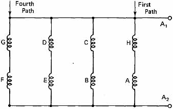
Figr. 3-10 Simplified schematic of a lap-wound armature.
With the connections above made, a schematic diagram of the armature can be drawn. It is shown in Figr. 3-9. Note that it's for the position that the armature is in at the instant shown in Figr. 3-8.
Figr. 3-9 can be redrawn to obtain a clearer picture. It is shown in Figr. 3-10. As can be seen, there are four parallel paths. If the picture was redrawn, an instant later after the armature had rotated 45 degrees, it would look the same except that there would be a different pair of coils in each path. The first path would contain A and B, the second C and D, the third E and F, and the fourth G and H. In any case the number of coils (turns or conductors) would be the same for each path. The following statements can be made for a lap-wound armature:
1. For a simplex lap winding there are as many parallel paths as there are poles.
2. Although not discussed here, a duplex lap winding would have twice as many parallel paths as there were poles, and a triplex lap winding would have three times as many paths as there were poles. Hence a four-pole triplex winding would have 12 parallel paths.
3. The number of coils on an armature isn't important. What is important is the total number of conductors (z) on the armature and the number of parallel paths.
4. The voltage generated by a lap-wound armature would be the voltage per path since all paths are in parallel.
5. The rated current of a lap-wound armature would be the rated current per path times the number of paths. The rated current per path is simply a function of the gauge of the wire used for the coils.
Example 3-1
An armature is wound simplex lap in a six-pole generator. The total number of conductors is 600. The resistance per conductor is 0.04 11 and the average induced voltage per conductor is 0.48 V. If the wire used is rated 15 A, find:
(a) The armature resistance
(b) The armature voltage
(c) The rated armature current
(d) The power output of the armature when supplying rated current
Solution
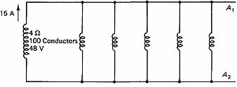
Figr. 3-11 Diagram for Example 3-1.
A six-pole simplex lap armature has six parallel equivalent paths, as shown by Figr. 3-11. Since there are a total of 600 conductors, each path must have 100 conductors. As can be seen in Figr. 3-10, the conductors in each path are in series. Therefore, the resistance per path would be (100 cond./path) x (0.04 Ω) = 4 Ω/path, the voltage per path would be (100 cond./path) X (0.48 V/cond.) = 48 V and each path could supply 15 A.
(a) The armature resistance would be the parallel combination of six 4-Ω resistors.
R4 = 4-Ω / 6 = 0.67 Ω
(b) Since the paths are in parallel, the armature voltage would be
Va = 48 V
(c) Since the paths are in parallel, the rated armature current would be
Ia = 6 paths x 15 A/path = 90 A
(d) When supplying rated current, the power output would be
P = Va x Ia
= 48 V x 90 A = 4320 W
3-6.2 Simplex Wave Singly Reentrant Winding
An analysis for the wave winding could be carried out in a way similar to that for the lap winding. It is, however, more difficult to visualize. We will therefore not go into the details of the wave-winding construction but rather highlight its characteristics.
1. For a simplex wave winding there will always be two parallel paths regardless of the number of poles.
2. A duplex wave winding will double the number of parallel paths present in the simplex. Thus there will be 2 x 2, or four parallel paths; the triplex wave winding will have 3 X 2, or six parallel paths; and so on.
3. Since there are always two parallel paths (simplex wave), the number of conductors per path will be the total number of armature conductors divided by 2.
4. The voltage generated by a simplex wave armature will be that due to half of the armature conductors since there are two paths.
5. Brushes of like polarity are always shorted out by a coil whose conductors are moving parallel to the lines of flux (zero voltage generated). Therefore, all that's needed is one pair of brushes, one positive and the other negative. An obvious advantage of the wave winding is the need for only two brushes. It makes it somewhat easier to construct.
6. The rated current of a simplex wave-wound armature would be twice the rated current per path. The rated current per path is simply a function of the gauge of the wire used for the coils.
Example 3-2
An armature is wound simplex wave in a six-pole generator. The total number of conductors is 600. The resistance per conductor is 0.04 fl and the average induced voltage per conductor is 0.48 V. If the wire used is rated 15 A, find:
(a) The armature resistance
(b) The armature voltage
(c) The rated armature current
(d) The power output of the armature when supplying rated current
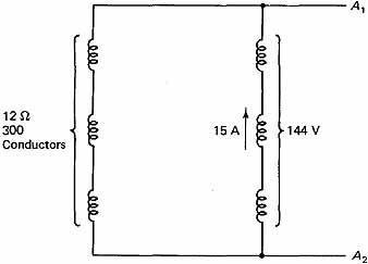
Figr. 3-12 Diagram for Example 3-2.
Solution
A simplex wave armature always has two parallel equivalent paths, as shown by Figr. 3-12. Since there are a total of 600 conductors, each path must have 300 conductors. As can be seen in Figr. 3-12, the conductors in each path are in series. Therefore, the resistance per path would be (300 cond./path) X (0.04 V/cond.) = 12 a/path, the voltage per path would be (300 cond./path) x (0.48 V/cond.) = 144 V/path and each path could supply 15 A.
(a) The armature resistance would be the parallel combination of two 12-Ω resistors.
Ra = 12 ohm / 2 = 6 Ω
(b) Since the paths are in parallel, the armature voltage would be
Va = 144 V
(c) Since the paths are in parallel, the rated armature current would be Ia = 2 paths x 15 A/path = 30 A
(d) When supplying rated current, the power output would be
P = Va x Ia
= 144 V x 30 A = 4320 W
3-6.3 Comparison of Lap and Wave Windings
In Sections 3-6.1 and 3-6.2 we examined an armature winding which was first connected simplex lap and then simplex wave. By comparing Examples 3-1 and 3-2, some general conclusions can be drawn.
1. Depending on how the armature is connected (lap or wave), very different characteristics are obtained. A lap-wound armature has a high current rating but generates a low voltage, whereas a wave winding will be used for lower currents and higher voltages. In either case, however, the power rating will be the same.
2. A simplex lap winding will have as many parallel paths as there are poles. The number of paths is further multiplied if the winding is duplex (x 2) or triplex (x 3). Therefore, an eight-pole duplex lap winding would have 16 (8 x 2) parallel paths.
3. A simplex wave winding will always have two parallel paths independent of the number of poles. The number of paths, however, gets multiplied if the winding is duplex (2 x 2) or triplex (3 x 2). Therefore, an eight-pole duplex wave winding would have four (2 x 2) parallel paths.
4. A two-pole armature wound simplex lap would have exactly the same characteristics and look exactly the same as a two-pole armature-wound simplex wave.
5. In the wave winding, since coils that are not generating a voltage electrically connect brushes of similar voltage polarity, only two brushes are required.
At this point, we can develop further a basic equation derived in Section 2. Equations 2-5 were used to solve for the average voltage generated by an armature with one coil having a total of z conductors. As we have seen in this section, the number of coils isn't important. What is important, in addition to the number of conductors, is the number of parallel paths. Therefore, Eqs. 2-5 will be rewritten here to include the number of parallel paths (a). The quantities z, Φ, P, S, and w have the same meaning and units as stated for Eqs. 2-5.
(English) (3-1a)
Eg = [z(Φ)PS x 10^-8] / 60a
(SI) (3-1b)
Eg = [z(Φ)PS(Ω)] / 2πa
Example 3-3 (English)
A six-pole generator has a total of 300 conductors. It is driven at 1800 rev/min and the flux per pole is 200 kilolines. Find the average voltage generated by the armature if it's wound:
(a) Simplex lap
(b) Simplex wave
Solution
The problem is solved by direct substitution into Eq. 3-1a. However, the number of parallel paths must first be determined.
(a) For the simplex lap the number of parallel paths is equal to the number of poles. Thus a = 6.
Eg = [300(200k)(6)(1800) x 10^-8] / 60 (6)
= 18V
(b) For the simplex wave the number of parallel paths is equal to two. Thus a = 2.
Eg = [300(200k)(6)(1800) x 10^-8] / 60 (2)
= 54 V
Example 3-4 (SI)
An eight-pole generator has a total of 300 conductors. It is driven at 180 rad/s and the flux per pole is 2 x 10^-3 Wb. Find the average voltage generated by the armature if it's wound:
(a) Simplex lap
(b) Simplex wave
Solution
The problem is solved by direct substitution into Eq. 3-lb. However, the number of parallel paths must first be determined.
(a) For the simplex lap the number of parallel paths is equal to the number of poles.
Thus a = 8.
Eg = [300(2 x 10^-3)(8)(180)/2π(8)]
= 17.2 V
(b) For the simplex wave the number of parallel paths is equal to two. Thus a = 2.
Eg = [300(2 x 10^-3)(8)(180)/2π(28)]
= 68.75 V
Example 3-5 (English)
A 32-pole generator has a wave-wound armature (a = 2) with 800 conductors. It is driven at 60 rev/min. Find the flux per pole necessary to generate an average armature voltage of 120 V.
Solution
Equation 3-1a will be used; however, it will first be rearranged to solve for the flux, (Φ).
Eg = [z(Φ)PS x 10^-8] / 60a
Solving for (Φ), we get
= 937.5 kilo-lines
Example 3-6 (SI)
A 32-pole generator has a wave-wound armature (a = 2) with 800 conductors. It is. driven at 6 rad/s. Find the flux per pole necessary to generate an average armature voltage of 120 V.
Solution
Equation 3-1b will be used; however, it will first be rearranged to solve for the flux, (Φ).
Eg = [z(Φ)PS(Ω)] / 2πa
Solving for (Φ), we get
= 0.0098 = 9.8 x 10^-3 Wb
Symbol |
Definition |
Units: English and SI |
a z Va Ra Ia Eg |
Number of parallel paths Number of armature conductors Armature voltage Armature resistance Full-load armature current Average (dc) generated voltage of a rotating armature (Note. Although neglected in this section, this is greater than Va by an amount equal to the internal voltage drop across Ra |
- - volts ohms amperes volts |
QUESTIONS
1. Define the following terms: armature; commutation; commutator segment; field poles.
2. What is the purpose of constructing the armature with laminated disks?
3. What is armature reaction?
4. Of what are brushes made?
5. What is the purpose of an interpole?
6. What are compensating windings?
PROBLEMS
(English and SI)
1. A four-pole generator has a simplex lap wound armature. It has a total of 480 conductors each rated 0.03 Ω/cond. The average generated voltage per conductor is 0.5 V. The wire used is rated 20 A. Find:
(a) The armature resistance
(b) The armature voltage
(c) The rated armature current
(d) The rated power of the armature
2. Repeat Problem 1 if the armature is simplex wave wound.
3. An eight-pole armature is wound simplex lap. It has a total of 1200 conductors, each having a resistance of 0.035 Ω. The average generated voltage per conductor is 0.56 V. If the conductors are rated 15 A, find:
(a) The armature resistance
(b) The armature voltage
(c) The rated armature current
(d) The rated power of the armature
4. Repeat Problem 3 if the armature is simplex wave wound.
5. A 12-pole armature wound simplex lap has 1620 conductors. Each conductor has a resistance of 0.1 Ω and generates an average voltage of 0.66 V. The conductors are rated 8 A.
Find:
(a) The armature resistance
(b) The armature voltage
(c) The rated armature current
(d) The rated power of the armature
6. Repeat Problem 5 if the armature is simplex wave wound.
7. The armature in an eight-pole generator is wound simplex lap. It is rated 230 V, 5 kW.
If it has a total of 1200 conductors and the total armature resistance is 0.8 1, find:
(a) The rated current per conductor
(b) The generated voltage per conductor
(c) The resistance per conductor
8. Repeat Problem 7 if the armature is simplex wave wound.
9. A 120-V 1-kW four-pole lap wound generator has a total of 720 conductors. If the total armature resistance is 1.0 Ω, find:
(a) The rated current per conductor
(b) The generated voltage per conductor
(c) The resistance per conductor
10. Repeat Problem 9 if the armature is simplex wave wound.
(English)
11. A 12 pole generator has a total of 600 conductors. It is driven at 1200 rev/mm and the flux per pole is 350 kilolines. Find the generated armature voltage if it's wound:
(a) Simplex lap
(b) Simplex wave
12. A four-pole generator has a total of 800 conductors. When it's driven at 1800 rev/mm, its armature generates 440 V. Find the required flux per pole if the armature is wound:
(a) Simplex lap
(b) Simplex wave
13. A six-pole generator has a total of 420 conductors and a flux per pole of 400 kilolines. Find the speed at which it must be driven to generate 120 V if the armature is:
(a) Simplex lap
(b) Simplex wave
14. A four-pole generator has a total of 1000 conductors and a flux per pole of 500 kilolines. When it's driven at 1200 rev/min the generated voltage is 200 V. Is the armature wound simplex lap, simplex wave, or neither?
15. A 12-pole generator has a total of 1800 armature conductors, flux per pole of 500 kilolines, and is driven at 1000 rev/mm. Find the generated voltage if the armature is wound:
(a) Simplex lap
(b) Simplex wave
(SI)
16. A 16-pole generator has a total of 800 conductors. It is driven at 120 rad/s and the flux per pole is 0.004 Wb. Find the generated armature voltage if it's wound:
(a) Simplex lap
(b) Simplex wave
17. A six-pole generator has a total of 900 conductors. When it's driven at 60 π rad/s, its armature generates 230 V. Find the required flux per pole if the armature is wound:
(a) Simplex lap
(b) Simplex wave
18. An eight-pole generator has a total of 640 conductors and a flux per pole of 5.5 X 10^-3
Wb. Find the speed it must be driven at to generate 460 V if the armature is wound:
(a) Simplex lap
(b) Simplex wave
19. A four-pole generator has a total of 1440 conductors and a flux per pole of 4.6 x 10^-3 Wb. When it's driven at 40 π rad/s the generated voltage is 265 V. Is the armature wound simplex lap, simplex wave, or neither?
20. A 16-pole generator has a total of 2240 armature conductors, flux per pole of 0.005 Wb, and is driven at 100 rad/s. Find the generated voltage if the armature is wound:
(a) Simplex lap
(b) Simplex wave