Home
Articles
Forum
Glossary
Books
Sitemap
 Right: Fig. 1(a)
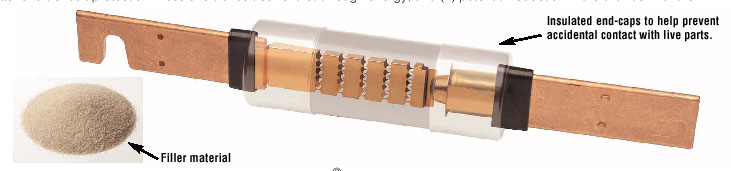
A cut-away picture of a dual-element fuse. Notice the time-delay element
consists of a spring-loaded trigger mechanism that is held in place
by solder. When the current is sufficient, it will melt the solder and the spring will open the fuse section. (b) The fuse is in the process
of opening during a slow overcurrent. (c) The slow overcurrent section
of the fuse has opened. (d) The short- circuit section of the fuse
sustains a short-circuit current. (e) The short-circuit link on the
right side of the fuse has opened after sustaining a short-circuit
current. The "open" Dual Element fuse after
opening under an overload condition.(c) Like the single element fuse,
a short-circuit current causes the restricted portions of the short-circuit
elements to melt and arcing to burn back the resulting gaps until the
arcs are suppressed by the arc quenching material and increased arc resistance.(d)
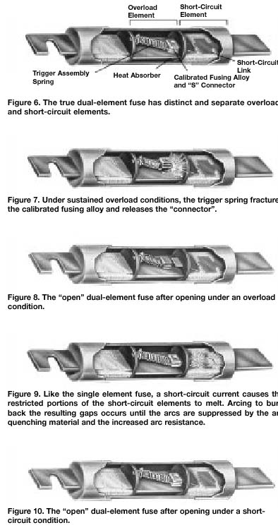
Overload Short-Circuit Element Short Trigger Assembly Heat Absorber Calibrated
Link Spring Fusing Alloy and “5” Connector The true dual-element fuse
has distinct and separate overload and short-circuit elements. Under
sustained overload conditions, the trigger spring fractures the calibrated
fusing alloy and releases the connector. (b)The “open” Dual Element fuse
after opening under a short circuit condition.
Right: Fig. 1(a)
A cut-away picture of a dual-element fuse. Notice the time-delay element
consists of a spring-loaded trigger mechanism that is held in place
by solder. When the current is sufficient, it will melt the solder and the spring will open the fuse section. (b) The fuse is in the process
of opening during a slow overcurrent. (c) The slow overcurrent section
of the fuse has opened. (d) The short- circuit section of the fuse
sustains a short-circuit current. (e) The short-circuit link on the
right side of the fuse has opened after sustaining a short-circuit
current. The "open" Dual Element fuse after
opening under an overload condition.(c) Like the single element fuse,
a short-circuit current causes the restricted portions of the short-circuit
elements to melt and arcing to burn back the resulting gaps until the
arcs are suppressed by the arc quenching material and increased arc resistance.(d)
Overload Short-Circuit Element Short Trigger Assembly Heat Absorber Calibrated
Link Spring Fusing Alloy and “5” Connector The true dual-element fuse
has distinct and separate overload and short-circuit elements. Under
sustained overload conditions, the trigger spring fractures the calibrated
fusing alloy and releases the connector. (b)The “open” Dual Element fuse
after opening under a short circuit condition.
The dual-element fuse provides the same short-circuit current protection as the single-element fuse along with time-delay protection against slow over-currents. Figure 1 shows cut-away pictures of a dual-element fuse. From these pictures notice that the dual-element fuse provides a short-circuit element and an overload element. Short-circuit elements (neck-down sections) are located on each end of the fuse, while the overcurrent element is located between them. The buildup won't damage the motor, and large overloads will be cleared quickly, since they will cause heat buildup that will permanently damage the motor. This design allows the motor to draw high inrush current, up to 500% of the full-load current for 10 seconds, which is adequate time to allow the motor to start. It will also allow the motor to develop extra horsepower to meet an increased load demand for several minutes, since the extra current that is drawn won't cause the fuse to open.
Figure 1a shows a normal dual-element fuse and notice the neck-down sections on each end and the time-delay element in the middle of the fuse. Figure 1b shows the excess heat of a slow overcurrent as it begins to loosen the spring- loaded time-delay element. Figure 1c shows the spring-loaded time-delay element has caused an open in the fuse.
Figure 1d shows the dual-element fuse has experienced a short-circuit current and an arc is established in the neck-down section. Figure 1e shows the neck-down section has opened and interrupted current flowing through the fuse.

