The three-wire control circuit is the most widely used motor control circuit. This circuit is similar to the two-wire circuit except it has an extra set of contacts that is connected in parallel around one of the original pilot switches to seal it in. The extra set of parallel contacts provides the third wire, which also gives this circuit its name. Learn to recognize this circuit when it's shown as a ladder diagram and as a wiring diagram. In this way you will be able to understand the operation of the circuit wherever it appears.
 Right: Fig.
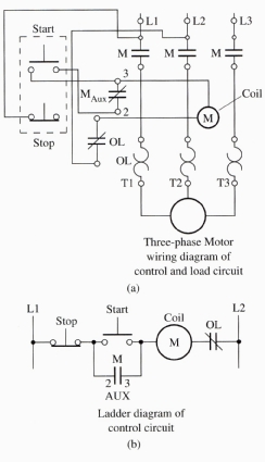
1(a) A typical three-wire control system. This control circuit gets its
name because of the auxiliary contacts that are connected in parallel with
the start button. The auxiliary contacts seal in the circuit to keep the
coil energized after the start push button is released. (b) Ladder diagram
of a three wire control circuit.
Right: Fig.
1(a) A typical three-wire control system. This control circuit gets its
name because of the auxiliary contacts that are connected in parallel with
the start button. The auxiliary contacts seal in the circuit to keep the
coil energized after the start push button is released. (b) Ladder diagram
of a three wire control circuit.
One variation of the three-wire circuit is shown in Figure 1. In this figure, stop and start push buttons are used as the pilot devices for control. Figure 1a shows the wiring diagram for the three-wire circuit, and Figure 1b shows the ladder diagram for the three-wire control circuit. In the ladder diagram notice that the stop push button is wired NC. When the start push button is depressed, voltage will flow through its contacts to energize the motor starter coil. When the coil becomes energized, it pulls its main contacts closed to cause the motor to become energized, and it also pulls its NO auxiliary contacts that are connected across the start push button to their closed position. When the auxiliary contacts close, they provide an alternate route for voltage to travel around the start push button contacts, which will return to their NO position when the switch is no longer depressed. The auxiliary contacts are called the seal-in circuit or in some cases the memory circuit. If the auxiliary contacts are not used, you would need to keep your finger on the start button to keep the circuit energized.
Notice in the three-wire circuit that the stop button is used to unseal the circuit and de-energize the motor starter coil. Anytime the stop button is depressed, the coil will become de-energized and the seal-in circuit will drop out. That is, the start push button must be depressed again to energize the circuit.
It's also important to understand in the three-wire circuit that the stop push button traditionally is always the first switch in the circuit. Most people assume this has something to do with safety. In reality, it has to do with economics. When you look at a motor starter, you will notice that the auxiliary contacts are physically located near the coil. If the start button is connected in the circuit next to the coil, the wire that is connected to the auxiliary contact on the right side (terminal 3) can actually be a short jumper wire that is connected directly to the left side of the coil. If the start button is not located next to the coil, the wires that connect the auxiliary contacts in parallel with the start push button will need to be as long as the distance between the start push button and the motor starter. This may be a distance of several hundred feet. This jumper wire is shown in the wiring diagram of the three-wire control circuit.

