AMAZON multi-meters discounts AMAZON oscilloscope discounts
Pilot devices are a group of components that include push-button switches, limit switches, and other switches commonly found in motor control circuits. These switches are called pilot devices because they are rated for control circuit voltage and current. That is, these switches will normally have 115 volts AC and less than 1 A current flowing through their contacts. The control circuits that use pilot duty switches are used to energize or de-energize the coil of a relay, motor starter, solenoid, or an indicator lamp. All of the loads in these circuits use low current. Again notice that the line-in voltage in your part of the country may be any value of voltage between 110 - 125 V AC. Henceforth, line voltages, for the discussions in this section, will be referred to as 115 V AC.
Fig. 1 shows a set of multiple push-button switches and selector switches that are pilot devices used to control a large industrial machine. The push buttons are the most commonly used switches to start and stop a machine, and selector switches are used to select the operation of the machine for such functions as manual or automatic operation.
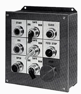
Above: Fig 1. A typical set of push button switches and selector
switches used to operate a machine.
Fig. 2 shows an exploded view of a typical push-button switch installation. From this diagram notice that the switch is actually an assembly of a number of parts including the push-button actuator that the operator presses on to activate the switch, a number of seals to keep moisture and other contaminants out of the switch assembly, and the contact block and contacts where the wires are actually connected. When the push-button activator is depressed, the contacts in the bottom of the switch will transition. If the switch has normally open contacts, they will go closed, and if the switch has normally closed contacts, they will go open. Some switches will have one set of contacts, while other switches have multiple sets of contacts. The important point to recognize is that all wires are connected to the contact block and the other parts of the switch can be changed without removing any wiring. This allows switches to be changed in the field with a minimum of down time for rewiring.
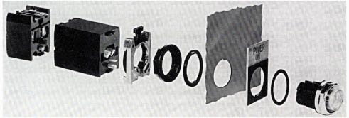
Above: Fig. 2 An exploded view of a typical switch. Notice that
the switch activation push button is shown above the panel where it's accessible
to the operator, and the remainder of the switch, including rubber seals, and the switch contacts are shown be low the panel.

