AMAZON multi-meters discounts AMAZON oscilloscope discounts
GOALS:
- Discuss the use of control transformers in a control circuit.
- Connect a control transformer for operation on a 240 or 480 volt system.
Primaries connected in parallel for 240 volt operation.
Most industrial motors operate on voltages that range from 240 to 480 volts. Magnetic control systems, however, generally operate on 120 volts. A control transformer is used to step the 240 or 480 volts down to 120 volts to operate the control system. There is really nothing special about a control transformer except that most of them are made with two primary windings and one secondary winding. Each primary winding is rated at 240 volts, and the secondary winding is rated at 120 volts.
This means there is a turns ratio of 2:1 (2 to 1) between each primary winding and the secondary winding. E.g., assume that each primary winding contains 200 turns of wire and the secondary winding contains 100 turns. There are two turns of wire in each primary winding for every one turn of wire in the secondary.
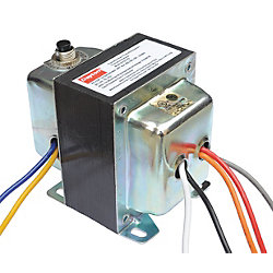
above: DAYTON Transformer, Ctrl, 120/208/240/480V, 75VA
One of the primary windings of the control transformer is labeled H1 and H2. The other primary winding is labeled H3 and H4. The secondary winding is labeled X1 and X2. If the transformer is to be used to step 240 volts down to 120 volts, the two primary windings are connected parallel to each other as shown in Fgr. 1. Notice that in Fgr. 1 the H1 and H3 leads are connected together, and the H2 and H4 leads are connected together. Since the voltage applied to each primary winding is the same, the effect is the same as having only one primary winding with 200 turns of wire in it. This means that when the transformer is connected in this manner, the turns ratio is 2:1. When 240 volts are connected to the primary winding, the secondary voltage is 120 volts.
If the transformer is to be used to step 480 volts down to 120 volts, the primary windings are connected in series. With the windings connected in series, the primary winding now has a total of 400 turns of wire, which makes a turns ratio of 4:1.
When 480 volts is connected to the primary winding, the secondary winding has an output of 120 volts.

Fgr. 1 Primaries connected in parallel for 240 volt operation

Fgr. 2 Primaries connected in series for 480 volt operation.

Fgr. 3 Primary leads are crossed.

Fgr. 4 Metal links used to make a 240 volt connection.
Control transformers generally have screw terminals connected to the primary and secondary leads. The H2 and H3 leads are crossed to make connection of the primary winding easier, Fgr. 3. E.g., if the transformer is to be connected for 240 volt operation, the two primary windings must be connected parallel to each other as shown in Fgr. 1.
This connection can be made on the transformer by using one metal link to connect leads H1 and H3, and another metal link to connect H2 and H4.
If the transformer is to be used for 480 volt operation, the primary windings must be connected in series as shown in Fgr. 2. This connection can be made on the control transformer by using a metal link to connect H2 and H3 as shown in Fgr. 5. A typical control transformer is shown.
Some control transformers contain a multi-tapped primary instead of two separate windings. The transformer in this example is designed to step voltages of 480, 277, 240, or 208 down to 120.

Fgr. 5 Metal link used to make a 480 volt connection.
Fgr. 6 Control transformer.

Fgr. 7 Control transformer with a multi-tapped primary winding.