AMAZON multi-meters discounts AMAZON oscilloscope discounts
Low-voltage Circuit Breakers
Circuit breakers are somewhat more sophisticated overload devices than are fuses. Although their function is the same as that of fuses, circuit breakers are much more versatile. In three-phase systems, circuit breakers can open all three hot lines when an overload occurs. They may also be activated by remote-control relays. Relay systems may cause circuit breakers to open in response to changes in frequency, voltage, current, or other circuit variables. Circuit breakers are used in industrial plants, and are usually of the low-voltage variety (less than 600 volts). They are not nearly as complex as their high-voltage counterparts (which were discussed previously). Most low-voltage circuit breakers are housed in molded-plastic cases that mount in metal power distribution panels. Circuit breakers are designed so that they will automatically open when a current occurs that exceeds the rating of the breaker. Ordinarily, the circuit breakers must be reset manually. Most circuit breakers employ either a thermal tripping element or a magnetic trip element. Ratings of circuit breakers extend into cur rent ranges that are as high as 800 to 2000 amperes.
Protective Relays
Protective relays provide an accurate and sensitive method of protecting electrical equipment from short circuits and other abnormal conditions. Overcurrent relays are used to cause the rapid opening of electrical power lines when the current exceeds a predetermined value. The response time of the relays is very important in protecting the equipment from dam age. Some common types of faults that relays protect against are line-to ground short circuits, line-to-line short circuits, double line-to-ground short circuits, and three-phase line short circuits. Each of these conditions is caused by faulty circuit conditions that draw abnormally high current from the power lines.
Motor Fault Current Protection
Motor fault currents are excessive currents that occur in motors as the result of some unnatural malfunction. Since motor fault currents can not be withstood for any duration of time, some type of protection must be provided to disconnect the motor from the power distribution system when a fault condition occurs. Such protection may be provided by motor starters, circuit breakers, or fuses. The type of protection used is dependent upon several characteristics of the power distribution system and the motor.
Motor Protective Devices
The distribution of electrical power to motors is a very important function of industrial and commercial power distribution. Distribution of energy to industrial electric motors is particularly important. Basic functions that motors are expected to perform are starting, stopping, reversing, and speed variation. These functions may be manually or automatically controlled. Various types of protective devices are used to provide for the efficient distribution of power to electric motors.
Overload protection is the most important motor protection function.
Such protection should serve the motor, its branch circuit, and the associated control equipment. The major cause of motor overload is an excessive mechanical load on the motor, which causes it to draw too much current from the power source. A block diagram of a motor-protection system is shown in FIG. 3.
Thermal overload relays are often used as protective devices. Thermal relays may be reset either manually or automatically. One type of thermal overload relay uses a bimetallic heater element. The bimetallic element bends as it is heated by the current flowing through it. When the cur rent reaches the rating of the element, the relay opens the branch circuit.
Another type of element is the melting alloy type. This device has contacts held closed by a ratchet wheel. At the current capacity of the device, the fusible alloy melts, causing the ratchet wheel to turn. A spring then causes the device to open the circuit.
Overheating Protection for Motors
Motors must be protected from excessive overheating. This protection is provided by magnetic or thermal protective devices, which are ordinarily within the motor-starter enclosure. Protective relays or circuit breakers can also perform this function. When an operational problem causes the motor to overheat, the protective device is automatically used to disconnect the motor from its power supply.
FIG. 3. Block diagram of a motor-protection circuit
Undervoltage Protection
Motors do not operate efficiently when less than their rated voltage is applied, and some types of motors can be destroyed if they are operated continuously at reduced voltages. Magnetic contactors (see Section 15) may be used effectively to protect against undervoltages. A specific level of voltage is required to cause magnetic contactors to operate. If the voltage is reduced below a specified level, the magnetic contactor will open, thus disconnecting the circuit between the power source and the motor, and stopping the motor before any damage can be done.
POWER DISTRIBUTION INSIDE INDUSTRIAL AND COMMERCIALBUILDINGS
Electrical power is delivered to the location where it is to be used, and then distributed within a building by the power distribution system.
Various types of circuit breakers and switchgear are employed for power distribution. Another factor involved in power distribution is the distribution of electrical energy to the many types of loads that are connected to the system. This part of the distribution system is concerned with the conductors, feeder systems, branch circuits, grounding methods, and protective and control equipment that is used.
Raceways
Most electrical distribution to industrial and commercial loads is through wires and cables contained in raceways. These raceways carry the conductors, which carry the power to the various equipment throughout a building. Copper conductors are ordinarily used for indoor power distribution. The physical size of each conductor is dependent upon the current rating of the branch circuit. Raceways may be large metal ducts or rigid metal conduits. These raceways provide a compact and efficient method of routing cables, wires, et cetera, throughout an industrial complex. A cable tray raceway design for industrial applications is shown in FIG. 4.
Feeder Lines and Branch Circuits
The conductors that carry current to the electrical load devices in a building are called feeders and branch circuits. Feeder lines supply power to branches, which are connected to them. Primary feeder lines may be either overhead or underground. Usually, overhead lines are preferred because they permit flexibility for future expansion. Underground systems cost more, but they help to maintain a more attractive environment. Secondary feeders are connected to the primary feeder lines, to supply power to individual sections within the building. Either aluminum or copper feeder lines may be used, depending on the specific power requirements. The distribution is from the feeder lines, through individual protective equipment, to branch circuits, which supply the various loads. Each branch circuit has various protective devices according to the needs of that particular branch. The overall feeder-branch system may be a very complex network of switching equipment, transformers, conductors, and protective equipment.
Switching Equipment
In addition to circuit protection, power distribution systems must have equipment that can be used to connect or disconnect the entire system or parts of the system. Various types of switching devices are used to perform this function. A simple type of switch is the safety switch. This type of switch is mounted in a metal enclosure and operated by means of an external handle. Safety switches are used only to turn a circuit off or on; however, fuses are often mounted in the same enclosure with the safety switch.
FIG. 4. Industrial cable tray raceway design (Chalfant Manufacturing
Co.)
Distribution Panelboards
Another type of switch is the kind used in conjunction with a circuit breaker panelboard. Panelboards are metal cabinets that enclose the main disconnect switch and the branch circuit protective equipment.
Distribution panelboards are usually located between the power feed lines within a building and the branch circuits that are connected to it.
Low-voltage Switchgear
Metal-enclosed low-voltage switchgear is used in many industrial and commercial buildings as a distribution control center to house the circuit breakers, bus bars, and terminal connections that are part of the power distribution system. Ordinarily, a combination of switchgear and distribution transformers is placed in adjacent metal enclosures. This combination is referred to as a load-center unit substation, since it is the central control for several loads. The rating of these load centers is usually 15,000 volts or less for the high-voltage section, and 600 volts or less for the low-voltage section. Load centers provide flexibility in the electrical power distribution design of industrial plants and commercial buildings.
Metal-enclosed switchgear, or metal-clad switchgear, is a type of equipment that houses all the necessary control devices for the electrical circuits that are connected to them. The control devices contained inside the switchgear include circuit breakers, disconnect switches, interconnecting cables and buses, transformers, and the necessary measuring instruments. Switchgear is used for indoor and outdoor applications at industrial plants, commercial buildings, and substations. The voltage ratings of switchgear are usually from 13.8 to 138 kV, with 1 to 10 MV A power ratings.
THE ELECTRICAL SERVICE ENTRANCE
Electrical power is brought from the overhead power lines, or from the underground cable, into a building by what is called a service entrance.
A good working knowledge of the National Electrical Code (NEC) specifications and definitions is necessary for an understanding of service entrance equipment. The NEC sets the minimum standards that are necessary for wiring design inside a building.
The type of equipment used for an electrical service entrance of a building may include high-current conductors and insulators, disconnect switches, protective equipment for each load circuit that will be connected to the main power system, and the meters needed to measure power, voltage, current, and/or frequency. It is also necessary to ground the power system at the service entrance location. This is done by a grounding electrode, which is a metal rod driven deep into the ground. The grounding conductor is attached securely to this grounding electrode.
Then, the grounding conductor is used to make contact with all neutral conductors and safety grounds of the system.
SERVICE ENTRANCE TERMINOLOGY
There are several terms associated with service entrance equipment. The service entrance conductors are a set of conductors brought to a building by the local electrical utility company. These conductors must be capable of carrying all of the electrical current that is to be delivered to the various loads inside the building that are to be supplied with power by the power system. Conductors that extend from the service entrance to a power distribution panel or other type of overcurrent protective equipment, are called feeders. Feeders are power lines that sup ply branch circuits. A branch circuit is defined as conductors that extend beyond the last overcurrent protective equipment of the power system.
Usually, each branch circuit delivers electrical power to a small percent age of the total load of the main power system.
In commercial and industrial installations, switchboards and panel boards are used to supply power to various loads throughout the power system. A switchboard is a large enclosure that has several overcurrent protective devices (fuses or circuit breakers). Each feeder is connected to the proper type of overcurrent device. Often, switchboards contain metering equipment for the power system. Panelboards are smaller than switchboards, but are used for a similar purpose. They are enclosures for overcurrent devices for either branch circuits or feeder circuits. A common example of a panelboard is the main power-distribution panel that houses the circuit breakers used for the branch circuits of a home. For more specific definitions of terms, you should refer to the most recent edition of the NEC.
Power Distribution System Components
Several specialized types of power distribution system components are available today and should be reviewed.
Uninterruptible Power Supply--An uninterruptible power sup ply (UPS) has computer-controlled diagnostics and monitoring to pro vide constant on-line power for today's modern equipment. The constant power capability is particularly useful for computer systems used in business and industry.
Power Filters and Conditioners--Power line filters ordinarily plug into interior power distribution systems. These filters have power out lets for obtaining filtered AC power. Power conditioners are also used to protect power distribution systems from spikes, surges, or other interference that may be damaging to certain types of equipment.
Floor-mounted Raceways--Floor-mounted raceways, surface race ways and power outlets, are used in most commercial and industrial facilities.
Conduit Connectors--Several types of conduit bodies are used to day. These bodies are used to provide a means of connecting conductors, and to allow angular bends in conduit runs throughout a building.
Wire Connectors--Simple but essential components of electrical power distribution systems are wire end connectors (sometimes called "wire nuts").
Plastic Components--Flexible plastic conduit provides an alternative to electrical metallic tubing (EMT) and rigid conduit, in certain distribution systems. Plastic boxes are compatible with flexible conduit and plastic enclosures for power distribution systems.
Power Outlets--Power outlets have standard configurations that have been established by the National Electrical Manufacturers Association (NEMA). The specific configuration indicates the voltage, current, and phase ratings of the distribution system. NEMA designs are shown in FIG. 5.
International Power Sources-an international power source provides a convenient means of converting North American voltage and frequency (120 volt/60 hertz) to international voltages and frequencies.
Output power is obtained through the appropriate standard international socket. The system shown has adjustable voltages and frequencies for obtaining power to match that of most countries, and for the use of products purchased in other countries, without modification of power supplies.
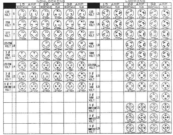
FIG. 5. Standard NEMA designs for power outlets (Pulizzi Engineering,
Inc.)
