AMAZON multi-meters discounts AMAZON oscilloscope discounts
When electrical power is distributed to its point of utilization, it is normally either in the form of single-phase or three-phase alternating cur rent (AC) voltage. Single-phase AC voltage is distributed into residences and smaller commercial buildings. Normally, three-phase AC voltage is distributed to industries and larger commercial buildings. Thus, the main types of power distribution systems are residential (single-phase) and industrial or commercial (three-phase).
An important aspect of both single-phase and three-phase distribution systems is grounding. Two grounding methods, system grounding and equipment grounding, will be discussed in this Section, along with ground fault protective equipment.
TERMINOLOGY
In this section (Section 10), single-phase and three-phase power distribution systems are discussed. After studying this Section, you should have an understanding of the following terms:
- Residential Distribution
- Commercial Distribution
- Industrial Distribution
- Single-Phase, Two-Wire Distribution System
- Single-Phase, Three-Wire Distribution System
- Hot Line
- Neutral
- System Ground
- Equipment Ground
- Insulation Color Identification
- Three-phase Delta-Delta Transformer Connection
- Three-phase Delta-Wye Transformer Connection
- Three-phase Wye-Wye Transformer Connection
- Three-phase Wye-Delta Transformer Connection
- Three-phase Open Delta Transformer Connection
- Three-phase, Three-Wire Distribution System
- Three-phase, Three-Wire, with Neutral Distribution System
- Three-phase, Four-Wire Distribution System
- "Wild" Phase
- Grounding Electrode
- Ground Fault Interrupter (GFI)
- Hand-to-Hand Body Resistance
- National Electrical Code (NEC)
- Electrical Inspection
- Voltage Drop of a Branch Circuit
- Branch Circuit
- Grounding Conductor
- Nonmetallic-Sheathed Cable (NMC)
- Metal-Clad Cable
- Rigid Conduit
- Electrical Metallic Tubing (EMT)
SINGLE-PHASE SYSTEMS
Most electrical power, when produced at the power plants, is produced as three-phase AC voltage. Electrical power is also transmitted in the form of three-phase voltage over long-distance power-transmission lines.
At its destination, three-phase voltage can be changed into three separate single-phase voltages for distribution into the residential areas.
Although single-phase systems are used mainly for residential power distribution systems, there are some industrial and commercial applications of single-phase systems. Single-phase power distribution usually originates from three-phase power lines, so electrical power systems are capable of supplying both three-phase and single-phase loads from the same power lines. FIG. 1 shows a typical power distribution system from the power station (source) to the various single-phase and three-phase loads that are connected to the system.
FIG. 1. A typical power distribution system.
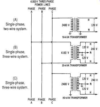
FIG. 2. Single-phase power distribution systems: (A) Single-phase,
two wire system, (B) Single-phase, three-wire system (taken from two
hot lines), (C) Single-phase, three-wire system (taken from one hot
line and one grounded neutral).
Single-phase systems can be of two major types-single-phase two wire systems or single-phase three-wire systems. A single-phase two-wire system is shown in FIG. 2A (the top diagram). This system uses a 10 kV A transformer whose secondary produces one single-phase voltage, such as 120 or 240 volts. This system has one hot line and one neutral line.
In residential distribution systems, this was the type most used to provide 120-volt service several years ago. However, as appliance power requirements increased, the need for a dual-voltage system was evident.
To meet the demand for more residential power, the single-phase three-wire system is now used. A home service entrance can be supplied with 120/240-volt energy by the methods shown in FIGs 2B and 10 2C (center and bottom diagrams). Each at these systems is derived from a three-phase power line. The single-phase three-wire system has two hot lines and a neutral line. The hot lines, whose insulation is usually black and red, are connected to the outer terminals of the transformer secondary windings. The neutral line (white insulated wire) is connected to the center tap of the distribution transformer. Thus, from neutral to either hot line, 120 volts for lighting and low-power requirements may be obtained.
Across the hot lines, 240 volts is supplied for higher-power requirements.
Therefore, the current requirement for large power-consuming equipment is cut in half, since 240 volts rather than 120 volts are used. Either the single-phase two-wire, or the single-phase three-wire system, can be used to supply single-phase power for industrial or commercial use. However, these single-phase systems are mainly for residential power distribution.
THREE-PHASE SYSTEMS
Since industries and commercial buildings use three-phase power predominantly, they rely upon three-phase distribution systems to supply this power. Large three-phase distribution transformers are usually located at substations adjoining the industrial plants or commercial buildings.
Their purpose is to supply the proper AC voltages to meet the necessary load requirements. The AC voltages that are transmitted to the distribution substations are high voltages, which must be stepped down by three phase transformers.
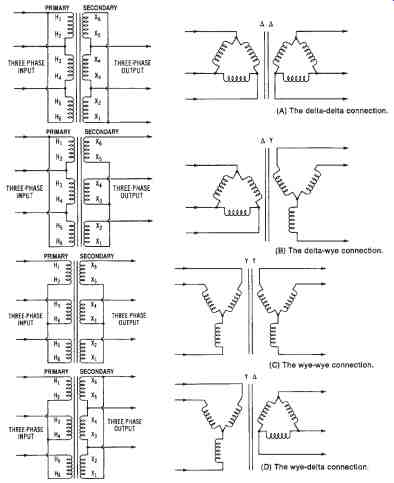
FIG. 3. Basic three-phase transformer connection methods: (A) The
delta-delta connection, (B) The delta-wye connection, (C) The wye-wye
connection, (D) The wye-delta connection, and (E) The open delta connection.
Three-phase Transformer Connections
There are five ways in which the primary and secondary windings of three-phase transformers may be connected. These are the delta-delta, the delta-wye, the wye-wye, the wye-delta, and the open-delta connections. These basic methods are illustrated in FIG. 3. The delta-delta connection ( FIG. 3A) is used for some lower-voltage applications.
The delta-wye method ( FIG. 3B) is commonly used for stepping up voltages, since the voltage characteristic of the wye-connected secondary results in an inherent step-up factor of 1.73 times. The wye-wye connection of FIG. 3C is ordinarily not used, while the wye-delta method ( FIG. 3D) may be used advantageously to step voltages down. The open-delta connection ( FIG. 3E) is used if one transformer winding becomes damaged, or is taken out of service. The transformer will still de liver three-phase power, but at a lower current and power capacity. This connection may also be desirable when the full capacity of three trans-formers is not needed until a later time. Two identical single-phase transformers can be used to supply power to the load until, at a later time, the third transformer is needed to meet increased load requirements.
Types of Three-phase Systems
Three-phase power distribution systems, which supply industrial and commercial buildings, are classified according to the number of phases and number of wires required. These systems, shown in FIG. 4, are the three-phase three-wire system, the three-phase three-wire system with neutral, and the three-phase four-wire system. The primary winding connection is not considered here. The three-phase three-wire system, shown in FIG. 4A, can be used to supply motor loads of 240 volts or 480 volts. Its major disadvantage is that it only supplies one volt age, as only three hot lines are sup plied to the load.
The usual insulation color code for these three hot lines is black, red, or blue, as specified in the NEC.
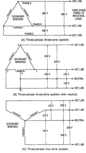
FIG. 4. Industrial power distribution systems: (A) Three phase, three-wire
system, (B) Three phase, three-wire system with neutral, (C) Three phase,
four-wire system.
The disadvantage of the three phase three-wire system may be partially over come by adding one center-tapped winding, as shown in the three-phase three-wire with neutral system of FIG. 4B. This system can be used as a supply for 120/240 volts or 240/480 volts. If we assume that it is used to supply 120/240 volts, the voltage from the hot line at point 1 and the hot line at point 2 to neutral would be 120 volts, because of the center-tapped winding.
However, 240 volts would still be available across any two hot lines. The neutral wire is color-coded with a white or gray insulation. The disadvantage of this system is that, when wiring changes are made, it is possible to connect a 120-volt load between the neutral and point 3 (sometimes called the "wild" phase). The voltage present here would be the combination of three-phase voltages between points 1 and 4 and points 1 and 3. This would be a voltage in excess of 300 volts! Although the "wild-phase" situation exists, this system is capable of supplying both high-power loads and low voltage loads, such as are used for lighting and small equipment.
The most widely used three-phase power distribution system is the three-phase four-wire system. This system, shown in FIG. 4C, commonly supplies 120/208 volts and 277/480 volts for industrial or commercial load requirements. The 120/208-volt system is illustrated here. From neutral to any hot line, 120 volts for lighting and low-power loads may be obtained. Across any two hot lines, 208 volts is present for supplying motors or other high-power loads. The most popular system for industrial and commercial power distribution is the 277/408-volt system, which is capable of supplying both three-phase and single-phase loads. A 240/416-volt sys tem is sometimes used for industrial loads, while the 120/208-volt system is often used for underground distribution in urban areas. Note that this system is based on the voltage characteristics of the three-phase wye connection, and that the relationship VL = VP × 1.73 exists for each application of this system.
GROUNDING OF DISTRIBUTION SYSTEMS
The concept of grounding in an electrical power distribution system is very important. Distribution systems must have continuous uninterrupted grounds. If a grounded conductor is opened, the ground is no longer functional. An open-ground condition can present severe safety problems and cause abnormal system operation.
Distribution systems must be grounded at substations, and at the end of the power lines, before the power is delivered to the load. Grounding is necessary at substations for the safety of the public and the power company's maintenance personnel. Grounding also provides points for transformer neutral connections for equipment grounds. Safety and equipment grounds will be discussed in more detail later.
At substations, all external metal parts must be grounded, and all transformer, circuit breaker, and switch housings must be grounded. Also, metal fences and any other metal that is part of the substation construction must be grounded. Grounding assures that any person who touches any of the metal parts will not receive a high-voltage shock. Therefore, if a high-voltage line were to come in contact with any of the grounded parts, the system would be opened by protective equipment. Thus, the danger of high voltages at substations is substantially reduced by grounding. The actual ground connection is made by welding, brazing, or bolting a conductor to a metal rod or bar, which is then physically placed in the earth. This rod device is called a grounding electrode. Proper grounding techniques are required for safety, as well as for circuit performance. There are two types of grounding: (1) system grounding, and (2) equipment grounding. Another important grounding factor is ground-fault protective equipment.
SYSTEM GROUNDING
System grounding involves the actual grounding of a current-carrying conductor (usually called the neutral) of a power distribution system.
Three-phase systems may be either the wye or delta type. The wye system has an obvious advantage over the delta system, since one side of each phase winding is connected to ground. We will define a ground as a reference point of zero-volt potential, which is usually an actual connection to earth ground. The common terminals of the wye system, when connected to ground, become the neutral conductor of the three-phase four-wire sys tem.
The delta-system does not readily lend itself to grounding, since it does not have a common neutral. The problem of ground faults (line-to ground shorts) occurring in ungrounded delta systems is much greater than in wye systems. A common method of grounding a delta system is to use a wye-delta transformer connection and ground the common terminals of the wye-connected primary. However, the wye system is now used more often for industrial and commercial distribution, since the secondary is easily grounded, and it provides overvoltage protection from lightning or line-to-ground shorts.
Single-phase 120/240-volt or 240/480-volt systems are grounded in a manner similar to a three-phase ground. The neutral of the single-phase three-wire system is grounded by a metal rod (grounding electrode) driven into the earth at the transformer location. System grounding conductors are insulated with white or gray material for easy identification.
Equipment Grounding
The second type of ground is the equipment ground, which, as the term implies, places operating equipment at ground potential. The conductor that is used for this purpose is either bare wire or a green insulated wire. The NEC describes conditions that require fixed electrical equipment to be grounded. Usually, all fixed electrical equipment located in industrial plants or commercial buildings should be grounded. Types of equipment that should be grounded include enclosures for switching and protective equipment for load control, transformer enclosures, electric motor frames, and fixed electronic test equipment. Industrial plants should use 120-volt, single-phase, duplex receptacles of the grounded type for all portable tools. The grounding of these receptacles may be checked by using a plug-in tester.
GROUND-FAULT PROTECTION
Ground-fault interrupters (GFIs) are used extensively in industrial, commercial, and residential power distribution systems. It is required by the NEC that all 120-volt, single-phase, 15- or 20-ampere receptacle outlets that are installed outdoors or in bathrooms have ground-fault interrupters connected to them. These devices are also called ground-fault circuit interrupters (GFCIs).
GFI Operation
These devices are designed to eliminate electrical shock hazard resulting from individuals coming in contact with a hot AC line (line-to ground short). The circuit interrupter is designed to sense any change in circuit conditions, such as would occur when a line-to-ground short exists.
One type of GFI has control wires that extend through a magnetic toroidal loop (see FIG. 5). Ordinarily, the AC current flowing through the two conductors inside the loop is equal in magnitude and opposite in direction. Any change in this equal and opposite condition is sensed by the magnetic toroidal loop. When a line-to-ground short occurs, an instantaneous change in circuit conditions occurs. The change causes a magnetic field to be induced into the toroidal loop. The induced current is amplified to a level sufficient to cause the circuit breaker mechanism to open. Thus, any line-to-ground short will cause the ground-fault interrupter to open.
The operating speed of the GFI is so fast that the shock hazard to individuals is greatly reduced, since only a minute current opens the circuit.
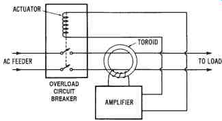
FIG. 5. Simplified schematic of a ground-fault interrupter
GFI Applications
Construction sites, where temporary wiring is set up, are required to use GFIs for the protection of workers using electrical equipment. Ground fault protection of individuals and commercial equipment must be pro vided for wye-connected systems of 150 to 600 volts for each distribution panelboard rated at over 1000 amperes. In this situation, the GFI will open all ungrounded conductors at the panelboard when a line-to-ground short occurs. Now, GFIs are used for all types of residential, commercial, and industrial applications.
Types of Ground-fault Protection Systems
There are four basic types of ground-fault protection systems in use today. They are: hospital applications, residential applications, motor protection applications, and specific electrical power distribution system applications. These ground-fault systems can be classified either by what they are to protect, or by the type of protection they are to provide. Hospital applications and residential applications are designed to protect people from excessive shock. The motor and electrical power applications are designed for protecting electrical equipment.
Another classification method is according to the amount of current required before an alarm system sounds, or the disconnect of an electrical circuit occurs. Typical current values that will cause alarms or disconnects to activate are 0.002 amperes (2 mA) for hospital applications, 0.005 amperes (5 mA) for residential applications, 5 to 100 amperes for motor-protective circuit applications, and 200 to 1200 amperes for electrical power distribution equipment applications.
Need for Ground-fault Protection
In order to understand the need for a ground-fault circuit interrupter (for the protection of people), certain basic facts must first be understood.
These facts relate to people as well as to ground faults.
One important fact is that a person's body resistance varies with the amount of moisture present on the skin, the muscular structure of the body, and the voltage to which the body is subjected. Experiments have shown that the body resistance from one hand to the other hand is some where between 1000 and 4000 ohms. These estimates are based upon several assumptions concerning moisture and muscular structure. We also know that resistance of the body (hand to hand) is lower for higher volt ages. This is because higher voltages are capable of "breaking down" the outer layers of the skin. Thus, higher voltages are more dangerous.
We can use Ohm's law to estimate that the typical current resulting from the average body resistance (from hand to hand) is about 115 mA at 240 volts AC, and about 40 mA at 120 volts AC. The effects of a 60-Hz AC on the human body are generally accepted to be as given in TABLE 1.
Ventricular fibrillation is an abnormal pattern of contraction of the heart. Once ventricular fibrillation occurs, it will continue, and death will occur within a few minutes. Resuscitation techniques, when applied immediately, can save a victim. Deaths caused by electrical shock account for a high percentage of the deaths that occur in the home and in industry. Many of these deaths are due to contact with low-voltage circuits (600 volts and under), mainly 120- and 240-volt systems.
=========
TABLE 1. Body Reaction to Alternating Current
Amount of Current Effect on Body 1 mA or less No sensation (not felt).
More than 5 mA Painful shock.
More than 10 mA Muscle contractions; could cause "freezing" to the electrical circuit for some people.
More than 15 mA Muscle contractions; could cause "freezing" to the electrical circuit for most people.
More than 30 mA Breathing difficult; could cause unconsciousness.
50 to 100 mA Ventricular fibrillation of the heart is possible.
100 to 200 mA Ventricular fibrillation of the heart is certain.
Over 200 mA Severe burns and muscular contractions; the heart is more apt to stop beating than to fibrillate.
1 ampere and above: Permanent damage to body tissues.
========
Ground-fault Protection for the Home
Ground-fault interrupters for homes are of three types: (1) circuit breaker, (2) receptacle, and (3) plug-in types. Ground-fault protection de-vices are constructed according to standards developed by the Underwriters' Laboratories. The GFI circuit breakers combine ground-fault protection and circuit interruption in the same over-current and short-circuit protective equipment as does a standard circuit breaker. A GFI circuit breaker fits the same space required by a standard circuit breaker. It provides the same branch-circuit wiring protection as the standard circuit breaker, as well as ground-fault protection. The GFI sensing system continuously monitors the current balance in the ungrounded (hot) conductor and the grounded (neutral) conductor. The current in the neutral wire becomes less than the current in the hot wire when a ground fault develops. This means that a portion of the circuit current is returning to ground by some means other than the neutral wire. When an imbalance in current occurs, the sensor (a differential current transformer) sends a signal to the solid state circuitry, which activates a trip mechanism. This action opens the hot line. A differential current as low as 5 mA will cause the sensor to send a fault signal and cause the circuit breaker to interrupt the circuit.
Ordinarily, GFI receptacles provide ground-fault protection on 120-, 208-, or 240-volt AC systems. The GFI receptacles come in 15- and 20-ampere designs. The 15-ampere unit has a receptacle configuration for use with 15-ampere plugs only. The 20-ampere device has a receptacle configuration for use with either 15- or 20-ampere plugs. These GFI receptacles have connections for hot, neutral, and ground wires. All GFI receptacles have a two-pole tripping mechanism, which breaks both the hot and the neutral load connections at the time a fault occurs.
The plug-in GFI receptacles provide protection by plugging into a standard wall receptacle. Some manufacturers provide units that will ?t either two-wire or three-wire receptacles. The major advantage of this type of unit is that it can be moved from one location to another.
Ground-fault Protection for Power Distribution Equipment
Ground faults can destroy electrical equipment if allowed to continue. Phase-to-phase short circuits and some types of ground faults are usually high current. Normally, they are adequately handled by conventional overcurrent protective equipment. However, some ground faults produce an arcing effect from relatively low currents that are not large enough to trip conventional protective devices. Arcs can severely bum electrical equipment. A 480- or 600-volt system is more susceptible to arcing dam age than a 120-, 208-, or 240-volt system, because the higher voltages sustain the arcing effect. High-current faults are quickly detected by conventional overcurrent devices. Low-current values must be detected by GFIs.
Ground faults that cause an arcing effect in the equipment are probably the most frequent faults. They may result from damaged or deteriorated insulation, dirt, moisture, or improper connections. They usually occur between one hot conductor and the grounded equipment enclosure, conduit, or metal housing. The line-to-neutral voltage of the source will cause current to flow in the hot conductor, through the arc path, and back through the ground path. The impedance of the conductor and the ground-return path (enclosure, conduit, or housing) depends on many factors. As a result, the fault-current value cannot be predicted. It can also increase or decrease as the fault condition continues.
It is apparent that many factors influence the magnitude, duration, and effect of an arcing ground fault. Some conditions produce a large amount of fault current, while others limit the fault current to a relatively small amount. Arc-current magnitude and the time that the arc persists can cause very great damage to equipment. Probably the more important factor is the time period of the arcing voltage, since the longer the arcing time, the more chance that the arcs will spread to different areas within the equipment.
Ground-current relaying is one method used to protect equipment from ground faults. Current flows through a load or fault along the hot and neutral conductors and returns to the source on these conductors-and, to some extent, along the ground path. The normal ground path current is very small. Therefore, essentially all the current flowing from the source is also returning on the same hot line and neutral conductors. However, if a ground fault occurs, the ground current will increase to the point where some current will escape through the fault and return via the ground path.
As a result, the current returning on the hot and neutral conductors is less than the amount going out. The difference is an indication of the amount of current in the ground path. A relay, which senses this difference in cur rents, can act as a ground-fault protective device.
Ground-fault Protection for Electric Motors
Motor protective systems offer protection in the 5- to 100-ampere range. This type of ground-fault protective system offers a protection against ground faults in both the single-phase and the three-phase systems. Many insulation system failures begin with a small leakage current, which builds up with time until damage results. These ground-fault systems detect ground leakage currents while they are still small, and thus prevent any extensive damage to the motors.
WIRING DESIGN CONSIDERATIONS FOR DISTRIBUTION SYSTEMS
The wiring design of electrical power distribution systems can be very complex. There are many factors that must be considered in the wiring de sign of a distribution system installed in a building. Wiring design standards are specified in the National Electrical Code (NEC), which is published by the National Electrical Protection Association (NEP A). The NEC, local wiring standards, and electrical inspection policies should be taken into account when an electrical wiring design is under consideration.
There are several distribution system wiring design considerations that are pointed out specifically in the NEC. In this Section, we will deal with voltage-drop calculations, branch circuit design, feeder circuit de sign, and the design for grounding systems.
National Electrical Code (NEC) Use
The NEC sets forth the minimum standards for electrical wiring in the United States. The standards contained in the NEC are enforced by being incorporated into the different city and community ordinances that deal with electrical wiring in residences, industrial plants, and commercial buildings. Therefore, these local ordinances conform to the standards set forth in the NEC.
In most areas of the United States, a license must be obtained by any individual who does electrical wiring. Usually, one must pass a test administered by the city, county, or state, in order to obtain this license.
These tests are based on local ordinances and the NEC. The rules for electrical wiring that are established by the local electrical power company are also sometimes incorporated into the license test.
Electrical Inspections
When new buildings are constructed, they must be inspected to see if the electrical wiring meets the standards of the local ordinances, the NEC, and the local power company. The organization that supplies the electrical inspectors varies from one locality to another. Ordinarily, the lo cal power company can advise individuals about whom to contact for in formation about electrical inspections.
Voltage Drop in Electrical Conductors
Although the resistance of electrical conductors is very low, a long length of wire could cause a substantial voltage drop. This is illustrated in FIG. 6. Remember that a voltage drop is current times resistance (I × R). Therefore, whenever current flows through a system, a voltage drop is created. Ideally, the voltage drop caused by the resistance of a conductor will be very small.
However, a longer section of electrical conductor has a higher resistance. Therefore, it is sometimes necessary to limit the distance a conductor can extend from the power source to the load that it supplies. Many types of loads do not operate properly when a value less than the full source voltage is available.
You can also see from FIG. 6 that as the voltage drop (VD) in creases, the voltage applied to the load (VL) decreases. As current in the system increases, VD increases, causing VL to decrease, since the source voltage stays the same.
TABLE 2. Sizes of Copper and Aluminum Conductors
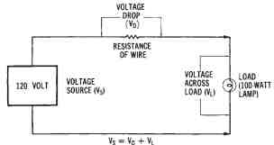
FIG. 6. Voltage drop in on electrical circuit
Voltage Drop Calculations Using Conductor Table
It is important when dealing with electrical wiring design to be able to determine the amount of voltage drop caused by conductor resistance.
TABLE 2 is used to make these calculations. The NEC limits the amount of voltage drop that a system can have. This means that long runs of conductors must ordinarily be avoided. Remember that a conductor with a large cross-sectional area will cause a smaller voltage drop, since its resistance is smaller.
To better understand how to determine the size of conductor required to limit the voltage drop in a system, we will look at a sample problem.
Sample Problem:
Given: a 200-ampere load located 400 feet (121.92 meters) from a 240-volt single-phase source. Limit the voltage drop to 2 percent of the source.
Find: the size of an RH copper conductor needed to limit the voltage drop of the system.
Solution:
1. The allowable voltage drop equals 240 volts times 0.02 (2%). This equals 4.8 volts.
2. Determine the maximum resistance for 800 feet (243.84 meters). This is the equivalent of 400 feet (121.92 meters) × 2, since there are two current-carrying conductors for a single-phase system.
3. Determine the maximum resistance for 1000 feet (304.8 meters) of conductor.
4. Use TABLE 2 to find the size of copper conductor that has the nearest direct current (DC) resistance (ohms per 1000 feet) value that is equal to or less than the value calculated in 3, above. The conductor chosen is conductor size 350 MCM, RH Copper.
5. Check this conductor with the proper ampacity table to ensure that it is large enough to carry 200 amperes. TABLE 3 shows that a 350 MCM, RH copper conductor will handle 310 amperes of current; therefore, use 350 MCM conductors. (Always remember to use the largest conductor, if Steps 4 and 5 produce conflicting values.)
6. If the current is larger than listed on the tables, use more than one conductor of the same size for design calculations.
TABLE 3. Ampacities of Conductors in a Raceway or Cable (3 or less)
Alternative Method of Voltage Drop Calculation
In some cases, an easier method to determine the conductor size for limiting the voltage drop is to use one of the following formulas to find the cross-sectional (cmil) area of the conductor.
...where:
p = the resistivity from TABLE 2
I = the load current in amperes,
VD = the allowable voltage drop, and
d = the distance from source to load, in feet.
The sample problem given for a single-phase system in the preceding section could be set up as follows:
The next largest size is a 350 MCM conductor.
BRANCH CIRCUIT DESIGN CONSIDERATIONS
A branch circuit is defined as a circuit that extends from the last over current protective device of the power system. Branch circuits, according to the NEC, are either 15,20,30,40, or 50 amperes in capacity. Loads larger than 50 amperes would not be connected to a branch circuit.
There are many rules in the NEC that apply to branch circuit design.
The following information is based on the NEC. First, each circuit must be designed so that accidental short circuits or grounds do not cause dam age to any part of the system. Then, fuses or circuit breakers are to be used as branch circuit overcurrent protective devices. Should a short circuit or ground condition occur, the protective device should open and interrupt the flow of current in the branch circuit. One important NEC rule is that No. 16 or No. 18 (extension cord) wire may be tapped from No. 12 or No. 14 conductors, but not from conductors larger than No. 12. This means that an extension cord of No. 16 wire should not be plugged into a receptacle that uses No. 10 wire. Damage to smaller wires (due to the heating effect) before the overcurrent device can open is eliminated by applying this rule. Lighting circuits are one of the most common types of branch circuits. They are usually either 15-ampere or 20-ampere circuits.
The maximum rating of an individual load (such as a portable appliance connected to a branch circuit) is 80 percent of the branch circuit current rating. Therefore, a 20-ampere circuit could not have a single load that draws more than 16 amperes. If the load is a permanently connected appliance, its current rating cannot be more than 50 percent of the branch circuit capacity-if portable appliances or lights are connected to the same circuit.
Voltage Drop in Branch Circuits
Branch circuits must be designed so that sufficient voltage is sup plied to all parts of the circuit. The distance that a branch circuit can ex tend from the voltage source or power distribution panel is, therefore, limited. A voltage drop of 3 percent is specified by the NEC as the maximum allowed for branch circuits in electrical wiring design.
The method for calculating the voltage drop in a branch circuit is a step-by-step process that is illustrated by the following problem. Refer to the circuit diagram given in FIG. 7.
Sample Problem:
Given: a 120-volt 15-ampere branch circuit supplies a load that consists of four lamps. Each lamp draws 3 amperes of current from the source.
The lamps are located at 10-foot (3.05-meter) intervals from the power distribution panel.
Find: the voltage across lamp number 4.
Solution:
1. Find the resistance for 20 feet (6.1 meters) of conductor (same as for 10-foot conductor × 2). No. 14 copper wire is used for 15-ampere branch circuits. From TABLE 2, we find that the resistance of 1000 feet (304.8 meters) of No. 14 copper wire is 2.57 ohms. Therefore, the resistance of 20 feet of wire is: [not shown]
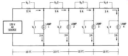
FIG. 7. Circuit for calculating the voltage drop in a branch circuit
Notice that the voltage across lamp number 4 is substantially reduced from the 120-volt source value because of the voltage drop of the conductors. Also, notice that the resistances used to calculate the voltage drops represented both wires (hot and neutral) of the branch circuit. Ordinarily, 120-volt branch circuits do not extend more than 100 feet (30.48 meters) from the power distribution panel. The preferred distance is 75 feet (22.86 meters). The voltage drop in branch circuit conductors can be reduced by making the circuit shorter in length, or by using larger conductors.
In residential electrical wiring design, the voltage drop in many branch circuits is difficult to calculate, since the lighting and portable appliance receptacles are placed on the same branch circuits. Since portable appliances and "plug-in" lights are not used all of the time, the voltage drop will vary according to the number of lights and appliances in use.
This problem is usually not encountered in an industrial or commercial wiring design for lights, since the lighting units are usually larger and are permanently installed on the branch circuits.
Branch Circuit Wiring
A branch circuit usually consists of a nonmetallic-sheathed cable that is connected into a power distribution panel. Each branch circuit that is wired from the power distribution panel is protected by a fuse or circuit breaker.
The power panel also has a main switch that controls all of the branch circuits that are connected to it.
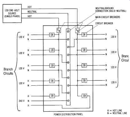
FIG. 8. Diagram of a power distribution panel for a single-phase,
three wire branch
Single-phase Branch Circuits
A diagram of a single-phase three-wire (120/240-volt) power distribution panel is shown in FIG. 8. Notice that eight 120-volt branch circuits and one 240-volt circuit are available from the power panel. This type of system is used in most homes, where several 120-volt branch circuits and, typically, three or four 240-volt branch circuits are required. Notice in FIG. 8 that each hot line has a circuit breaker, while the neutral line connects directly to the branch circuits. Neutrals should never be opened (fused). This is a safety precaution in electrical wiring design.
Three-phase Branch Circuits
A diagram for a three-phase, four-wire (120/208-volt) power distribution panel is shown in FIG. 9. There are three single-phase 120-volt branch circuits, and two three-phase 208-volt branch circuits shown. The single-phase branches are balanced (one hot line from each branch). Each hot line has an individual circuit breaker. Three-phase lines should be connected so that an overload in the branch circuit will cause all three lines to open. This is accomplished by using a three-phase circuit breaker, which is arranged internally as shown in FIG. 9.
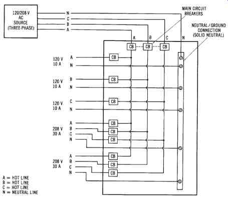
FIG. 9. Diagram of a power distribution panel for a three-phase, four-wire
branch circuit.
FEEDER CIRCUIT DESIGN CONSIDERATIONS
Feeder circuits are used to distribute electrical power to power distribution panels. Many feeder circuits extend for very long distances; there fore, voltage drop must be considered in feeder circuit design. In higher voltage feeder circuits, the voltage drop is reduced. However, many lower voltage feeder circuits require large-diameter conductors to provide a tolerable level of voltage drop. High-current feeder circuits also present a problem in terms of the massive overload protection that is sometimes required. This protection is usually provided by system switchgear or load centers where the feeder circuits originate.
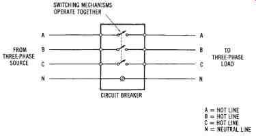
FIG. 10. Diagram of a three-phase circuit breaker
Determining the Size of Feeder Circuits
The amount of current that a feeder circuit must be designed to carry depends upon the actual load demanded by the branch circuit power distribution panels that it supplies. Each power distribution panel will have a separate feeder circuit. Also, each feeder circuit must have its own over load protection.
The following problem is an example of size calculation for a feeder circuit.
Sample Problem:
Given: three 15-kW fluorescent lighting units are connected to a three-phase, four-wire (277/480-volt) system. The lighting units have a power factor of 0.8.
Find: the size of THW aluminum feeder conductors required to sup ply this load.
Solution:
1. Find the line current:
PT
IL = ------- 1.73 × VL × pf
45, 000 watts
= --------- 1.73 × 480 volts × 0.8
= 67.74 amperes
2. From TABLE 3, we find that the conductor size that will carry 67.74 amperes of current is a No. 3 AWG THW aluminum conductor.
Voltage Drop Calculation for Feeder Circuits
Feeder circuit design must take the conductor voltage drop into consideration. The voltage drop in a feeder circuit must be kept as low as possible so that maximum power can be delivered to the loads connected to the feeder system. The NEC allows a maximum 5 percent voltage drop in the combination of a branch and a feeder circuit; however, a 5 percent voltage reduction represents a significant power loss in a circuit. We can calculate power loss due to voltage drop as V2/R, where V2 is the voltage drop of the circuit, and R is the resistance of the conductors of the circuit.
The calculation of feeder conductor size is similar to that for a branch circuit voltage drop. The size of the conductors must be large enough to: (1) have the required ampacity, and (2) keep the voltage drop below a specified level. If the second requirement is not met, possibly because of a long feeder circuit, the conductors chosen must be larger than the ampacity rating requires. The following problem illustrates the calculation of feeder conductor size based upon the voltage drop in a single-phase circuit.
Sample Problem:
Given: ex single-phase 240-volt load in a factory is rated at 85 kilo watts. The feeders (two hot lines) will be 260-foot (79.25 meters) lengths of RHW copper conductor. The maximum conductor voltage drop allowed is 2 percent.
Find: the feeder conductor size required.
Solution:
1. Find the maximum voltage drop of the circuit.
VD = % × Load
= 0.02 × 240
= 4.8 volts
2. Find the current drawn by the load.
Power
I = ---- Voltage
85,000
= --- 240
= 354.2 amperes
3. Find the minimum circular-mil conductor area required. Use the formula given for finding the cross-sectional area of a conductor in single-phase systems, which was previously given in the "Alternative Method of Voltage Drop Calculation" section.
cmil = p × I × 2d
----- VD
10.4 × 354.2 × 2 × 260
= ---------- 4.8
= 399,065.33 cmil
4. Determine the feeder conductor size. The next larger size conductor in TABLE 2 is also 400 MCM. Check TABLE 3, and you will see that a 400 MCM RHW copper conductor will carry 335 amperes. This is less than the required 354.2 amperes, so use the next larger size, which is a 500 MCM conductor.
The conductor size for a three-phase feeder circuit is determined in a similar way. In this problem, the feeder size will be determined on the basis of the circuit voltage drop.
Sample Problem:
Given: ex 480-volt, three-phase, three-wire (delta) feeder circuit sup plies a 45kilowatt balanced load to a commercial building. The load operates at a 0.75 power factor. The feeder circuit (three hot lines) will be a 300 foot (91.44-meter) length of RH copper conductor. The maximum voltage drop is 1 percent.
Find: the feeder size required (based on the voltage drop of the circuit).
Solution:
1. Find the maximum voltage drop of the circuit.
VD = 0.01 × 480
= 4.8 volts
2. Find the line current drawn by the load.
P
IL = ------ 1.73 × V × pf
45,000 W = ------- 1.73 × 480 × 0.75
= 72.25 amperes
3. Find the minimum circular-mil conductor area required. Use the formula for finding cmil in three-phase systems, which was given in an earlier section.
p × I × 1.73 d
cmil = ------ VD
10.4 × 72.25 × 1.73 × 300
= ----------- 4.8
= 81,245 cmil
4. Determine the feeder conductor size. The closest and next larger conductor size in TABLE 3 is No. 1 AWG. Check TABLE 3, and you will see that a No. 1 AWG RH copper conductor will carry 130 amperes, much more than the required 72.25 amperes. Therefore, use No. 1 AWG RH copper conductors for the feeder circuit.
DETERMINING GROUNDING CONDUCTOR SIZE
Grounding considerations in electrical wiring design were discussed previously. Another necessity of wiring design is to determine the size of the grounding conductor required in a circuit. All circuits that operate at 150 volts or less must be grounded; therefore, all residential electrical systems must be grounded. Higher voltage systems used in industrial and commercial buildings have grounding requirements that are specified by the NEC and by local codes. A ground at the service entrance of a building is usually a metal water pipe that extends, uninterrupted, underground, or a grounding electrode that is driven into the ground near the service entrance.
The size of the grounding conductor is determined by the current rating of the system. TABLE 4 lists equipment grounding conductor sizes for interior wiring, while TABLE 5 lists the minimum grounding conductor sizes for system grounding of service entrances. The sizes of grounding conductors listed in TABLE 4 are for equipment grounds, which connect to raceways, enclosures, and metal frames for safety purposes. Note that a No. 12 or a No. 14 wiring cable, such as 12-2 WG NMC, can have a No. 18 equipment ground. The ground is contained in the same cable sheathing as the hot conductors. TABLE 5 is used to find the minimum size of grounding conductors needed for service entrances, based upon the size of the hot line conductors used with the system.
PARTS OF INTERIOR ELECTRICAL WIRING SYSTEMS
Some parts of interior electrical distribution systems have been discussed previously. Such types of equipment as transformers, switchgear, conductors, insulators, and protective equipment are parts of interior wiring systems. There are, however, certain parts of interior electrical distribution systems that are unique to the wiring system itself. These parts include the nonmetallic-sheathed cables (NMC), the metal-clad cables, the rigid conduit, and the electrical metallic tubing (EMT).
TABLE 4. Equipment Grounding Conductor Sizes for Interior Winding
TABLE 5. System Grounding Conductor Sizes for Service Entrances
Nonmetallic-sheathed Cable (NMC)
Nonmetallic-sheathed cable is a common type of electrical cable used for interior wiring. NMC, sometimes referred to as Romex cable, is used in residential wiring systems almost exclusively. The most common type used is No. 12-2 WG, which is illustrated in FIG. 11. This type of NMC comes in 250-foot rolls for interior wiring. The cable has a thin plastic outer covering with three conductors inside. The conductors have colored insulation that designates whether the conductor should be used as a hot, neutral, or equipment ground wire. For instance, the conductor connected to the hot side of the system has black or red insulation, while the neutral conductor has white or gray insulation. The equipment grounding conductor has either a green insulation or no insulation (bare conductor). There are several different sizes of bushings and connectors used for the installation of NMC in buildings.
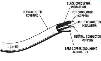
FIG. 11. Nonmetallic-sheathed cable (MNC)
The designation No. 12-2 WG means that (1) the copper conductors used are No. 12 AWG, as measured by an American wire gage (AWG), (2) there are two current-carrying conductors, and (3) the cable comes with a ground (WG) wire. A No. 14-3 WG cable, in comparison, would have three No. 14 conductors and a grounding conductor. NMC ranges in size from No. 14 to No. 1 AWG copper conductors, and from No. 12 to No. 2 AWG aluminum conductors.
Metal-Clad Cable
Metal-clad cable is similar to NMC except that it has a flexible spiral metal covering, rather than a plastic covering. A common type of metal clad cable is called BX cable. Like NMC, BX cable contains two or three conductors. There are also several sizes of connectors and bushings used in the installation of BX cable. The primary advantage of this type of met al-clad cable is that it is contained in a metal enclosure that is flexible, so that it can be bent easily. Other metal enclosures are usually more difficult to bend.
Rigid Conduit
The exterior of rigid conduit looks like water pipe. It is used in special locations for enclosing electrical conductors. Rigid conduit comes in 10-foot lengths, which must be threaded for joining the pieces together. The conduit is secured to metal wiring boxes by locknuts and bushings. It is bulky to handle and takes a long time to install.
Electrical Metallic Tubing (EMT)
EMT, or thin-wall conduit, is somewhat like rigid conduit, except that it can be bent with a special conduit-bending tool. EMT is easier to install than rigid conduit, since no threading is required. It also comes in 10-foot lengths. EMT is installed by using compression couplings to connect the conduit to metal wiring boxes. Interior electrical wiring systems use EMT extensively, since it can be easily bent, can be connected together, and can be connected to metal wiring boxes.
