AMAZON multi-meters discounts AMAZON oscilloscope discounts
.
4. Electrical Constants
The following electrical constants are used in the application of power cables.
Positive- and negative-sequence resistance
The resistance of a conductor to positive- and negative-sequence currents is affected by the following factors.
Skin effect: This effect is due to unequal distribution of alternating current (AC) flowing in a conductor because of the tendency of the current to flow more on the outside than inside strands of the conductor. This results in a higher resistance to AC than direct current (DC). Usually this effect can be neglected in smaller conductors.
Proximity effect: This effect is due to alternating magnetic flux produced by circulating current in a conductor caused by the current flowing in a neighboring conductor. This effect increases the resistance of a conductor. It can become pronounced where cables are installed parallel to metal beams, plates, walls, and the like.
Sheath currents: The alternating current (AC) flowing in a sheathed single conductor induces voltage in the sheath. Since the sheath is bonded and grounded at both ends, currents flow longitudinally, causing I2R losses. One way to account for these losses is to increase the resistance of the conductor.
Positive- and negative-sequence reactance
The reactance of a single lead-sheath conductor to positive- and negative sequence current can be calculated by taking into account the effect of sheath currents. It can be expressed mathematically by the following:
12ads/mile/phase XXXXX ==+-O where
X1 is the positive-sequence reactance X2 is the negative-sequence reactance Xa is the self-reactance of conductor at 1 ft radius Xd is the reactance of conductor beyond 1 ft radius Xs is the equivalent reactance value due to sheath currents For three-phase conductors, Xs can be neglected and the positive and negative reactances are X1 = X2 = Xa + Xd O/mile/phase.
Zero-sequence resistance and reactance
When zero-sequence currents flow in the three-phase system, the return path is usually either through the earth ground, sheath, ground wire, or a combination of these paths. In actual installation, the following combination of paths should be considered:
1. All currents in the ground, none in sheath
2. All currents in the sheath, none in ground
3. All currents in sheath and ground
When low-voltage cables are installed in magnetic ducts, the zero-sequence resistance and reactance are influenced by the magnetic material surrounding the conductor. No methods have been developed yet to accurately calculate the zero-sequence impedance. However, test data are available to give the required zero-sequence impedance data in standard reference handbooks on transmission and distribution of electrical power for various sizes of cables.
Shunt capacitance reactance
The positive-, negative-, and zero-sequence shunt capacitive reactances of cable are the same and can be expressed mathematically as follows:
===
where K is the dielectric constant X1, X2, and X0 are positive-, negative-, and zero-sequence reactances C1, C2, and C0 are positive-, negative-, and zero-sequence capacitive reactances G is the conductance of the cable f is the frequency of the power system
…
where I1, I2, and I0 are positive-, negative-, and zero-sequence charging currents.
Insulation resistance
The insulation resistance of the cable is very difficult to calculate because of varying insulation properties. However, a generalized formula can be expressed in terms of the power factor (PF) of the insulation system. For single-conductor cable,
…
and for three-conductor belted cable,
…where
r1, r2, and r0 are positive-, negative-, and zero-sequence shunt resistances G is the geometric factor K is the dielectric constant cos q is the insulation PF per unit
5. Cable Ratings
A basic knowledge of cable ratings is very important in order to select and apply cables for distribution and utilization of power. The following brief description of cable ratings will provide the basis for selecting and applying cables.
Continuous current-carrying rating The current-carrying capacity of cable is affected by several factors:
1. Maximum allowable temperature
2. Total watt loss (I2Rc) of the cable
3. Ability to dissipate heat
4. Ambient temperature
The maximum conductor temperature is determined by the maximum
temperature the insulation system can withstand for extended periods of time without damage. The maximum temperature in turn can be affected by the ability to dissipate heat and the ambient temperature of the medium in which the cable is installed to operate. The sum of ambient temperature and temperature rise in the insulation system should not exceed the total allowable temperature of the conductor for safe operation. Aluminum conductors can be expressed in terms of copper conductors for purposes of current-carrying capacity. The conversion factors to convert the current capacity of the same size aluminum conductor as copper can be expressed in terms of the resistance ratio of copper to aluminum, that is, RCu/RAl , where RCu and RAl are, respectively, the resistance of copper and aluminum conductors at rated temperature. The effect of temperature on current rating is shown in FIG. 5.
As the temperature of the conductor goes up, so does its resistance. The total loss of the cable is a function of the effective resistance of the conductor at maximum allowable temperature.
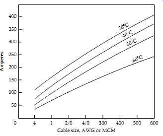
FIG. 5 Effect of ambient temperature on current rating.
Emergency current-carrying rating
The service life of cable is based upon its normal loading limits and normal operating temperature. The normal life expectancy of a cable insulation system is approximately 30 years. However, if the cable system is operated at 5°C-10°C above its temperature rating, it is to be expected that the cable life expectancy will be halved and its average rate of failure doubled. Another disadvantage in operating cables over their temperature rating is that copper loss is directly proportional to the square of current and resistance.
Furthermore, because of increased resistance and current, the voltage drop may be excessive and may jeopardize equipment and service continuity. Any program to operate the cables beyond the limit of their current and tempera ture ratings must be judiciously undertaken. To calculate the emergency rating of cables, the following formula may be used:
Jo is the emergency overload current jc is the continuous current to is the emergency overload temperature ta is the ambient temperature tc is the maximum operating temperature Rc is the conductor resistance at maximum operating temperature Ro is the conductor resistance at emergency overload temperature Overloading should be less than 100 h/year. Rubber-insulated cables may be operated at overloading temperature in accordance with TABLE 1.
Voltage rating
The voltage ratings of cables are specified as the line-to-line voltage that they can withstand. However, the insulation thickness is based upon line-to ground voltage. To specify the system voltage for procurement and installation of cables is not sufficient. It is necessary to specify also the type of system that the cable will use. Assume a cable application on a grounded 15 kV system, for which the insulation will be based upon line-to-ground voltage, that is 15/1.73 = 8.66 kV. Whereas on a 15 kV ungrounded system, the insulation thickness will be based on 15 kV because that is the voltage imposed on unfaulted conductors. The basis for voltage thickness for 15 kV belted cable operating at 13.8 kV grounded system is illustrated in FIG. 6.
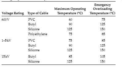
TABLE 1 Emergency Overload Temperature of Rubber-Insulated Cables
Short-circuit rating
All cable systems have thermal limitations, which are specified in terms of short-circuit withstand temperatures and current ratings. Under a short- circuit condition, the temperature of the conductor rises very rapidly. If the conductor is not sized to withstand the available short-circuit current, it will melt, resulting in cable failure. Because of the insulation sheath surrounding the conductor and its characteristics, it will cool off very slowly after the fault has been removed. The temperatures shown in TABLE 1 should not be exceeded per standards of the Insulated Cable Engineering Association (ICEA) for more than 10 s. Cable manufacturers publish current-withstand ratings for all sizes of conductors. The NEC requires that systems should be designed to have full withstand capability. Every cable installation should be checked for short-circuit withstand rating; otherwise, severe damage or complete failure may result. Failure may be accompanied by i re and smoke, thus resulting in danger to personnel and property. Also, because of thermal expansion due to intense heat under short-circuit conditions, the cable may be permanently damaged if not correctly selected for this purpose.
---
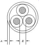
FIG. 6 Insulation thickness for three-phase belted cable.
In this type of construction each conductor insulation is based on one-half line-to-line voltage. The belt insulation is based upon the difference of line-to-ground voltage minus one-half the line-to line voltage. he overall thickness of insulation is the sum of the belt and conductor thickness.
---