AMAZON multi-meters discounts AMAZON oscilloscope discounts
__8.1.3 Relays
The failure modes of electromechanical and induction type relays are addressed here. Relays parts include both electrical parts, in the form of coils, connectors, and contacts, as well as mechanical parts, such as contact carriers, linkages, and supports. Wear of both the electrical and mechanical parts can occur due to repeated cycling of the relay. Degradation to the mechanical parts can result in misalignment, bending, or twisting of the parts.
Degradation of the electrical components can include shorting of the coils or pitting of the contacts. This degradation may result in degraded relay performance or complete loss of function. Switchgear relays are often mounted in switchgear assembly cabinet doors along with other electrical components. The heat generated from the components, combined with the effects of being in a confined space can often lead to temperatures that are significantly higher than ambient. Therefore, even though the relays may not be in a harsh location, a significant stressor for these components is elevated temperature. Also, relays that are constantly energized will experience an increased level of thermal degradation of temperature-sensitive materials.
The coil insulation is the primary concern for degradation due to elevated temperature. Continual cycling of relays can result in loosening of parts or electrical connections, or weakening of springs. If electrical connections become loose, this can lead to increased resistance and higher operating temperatures. Failure modes for relays are:
- Failure to close
- Failure to open
- Spurious signal
- Failure to operate as required
- Out of calibration
TABLE 8 summarizes the failure modes and characteristics of switchgear relays.
__8.1.4 Switchgear Buses
Electrical buses are an integral part of the medium-voltage switchgear and are used as a connection point to distribute electric power to various parts of the facility. A bus consists of metallic bus bars which are energized at the rated nominal system voltage level. The bus bars are usually made of solid copper metal bar that are silver and/or zinc plated, metal tubing, or flexible cable and are supported by insulators. Depending on the voltage and current levels at which they will operate, the bus bars may be wrapped in insulation or enclosed is a separate duct. Cable leads are attached to the bus to connect the various loads to be supplied. Aging stressors that may cause degradation of electrical buses primarily include exposure to moist or humid air, which can lead to corrosion of the metallic components, as well as exposure to high voltage arcing, which can degrade the various insulators used to support and isolate the bus bars. Vibration and thermal cycling can also lead to loosening of connections. Electrical transients can produce substantial electro magnetic forces that can crack, damage, or displace bus support insulators, connections, and associated hardware to secure these supports. Some examples of failure causes for electrical buses are listed below. TABLE 9 summarizes the aging characteristics of electrical buses.
- Short to ground
- Phase-to-phase short
- Corona and tracking
===================
TABLE 8 Failure Modes, Stressors, and Effects of Medium-Voltage Switchgear Relays
Component Material Stressors Failure Modes Effects Enclosure Phenolic, Lexan, aluminum, steel Elevated temperature Corrosion Loss of structural integrity Moisture/humidity Oxidation Dirt/moisture intrusion into internal components Mechanical stress Cracking of welds Seismic/vibration-induced damage Coil wire Polyamide/polyimide insulation, copper magnet wire Elevated temperature Embrittlement/cracking of insulation Loss of dielectric integrity Ohmic heating Corrosion/oxidation of wire Moisture/humidity Coil spool Zytel, Nylon, Lexan Elevated temperature Aging/cyclic fatigue, wear/loosening Improper operation of relay Mechanical stress due to cycling Coil coating Polyester or fiberglass tape varnish Elevated temperature Embrittlement/cracking Improper operation of relay Ohmic heating Contacts Silver Electrical arcing/cycling Pitting Increased temperature due to high resistance Electrical overload Corrosion/oxidation Improper operation due to misalignment of contacts Moisture/humidity Chatter-induced damage
Vibration Bending/twisting of linkage Mechanical stress Contact carrier/arm Phenolic, Zytel, Delrin, Nylon Mechanical stress due to cycling Embrittlement/cracking Improper/loss of relay function Distortion Coil lead wires capacitors Tel on, silicon rubber, Tefzel, insulation Electrical cycling Embrittlement/cracking of wire insulation Improper/loss of relay function Electrical overload Degradation of fuses Elevated temperature Wear/loosening of connections Moisture/humidity Vibration induced Slip motor rotor/bearings Bronze, copper Moisture/humidity Corrosion/oxidation Improper/loss of relay function Mechanical stress Bending/twisting Damping magnet Magnetic steel Moisture/humidity Corrosion/oxidation Improper/loss of relay function Mechanical stress Timing motor/ bearings Magnet wire with formal varnish Elevated temperature Embrittlement/cracking of winding insulation Loss of relay function due to shoring of motor windings Moisture/humidity Cams Delrin, Metal Moisture/humidity Corrosion/oxidation Improper/loss of relay function Timing diaphragms Silicon rubber Elevated temperature Embrittlement/cracking Improper/loss of relay function Mechanical stress due to cycling
==================
TABLE 9 Failure Modes, Stressors, and Effects of Medium-Voltage Switchgear Bus
Component Material Stressors Failure Modes Effects Conductor Aluminum copper Moisture/humidity Corrosion Loss of structural integrity Elevated temperature Oxidation Loss of electrical continuity Vibration Cracking of welds Reduced electrical clearance Electrical transients Seismic/vibration-induced damage Distortion and displacement Enclosure Aluminum polymers Moisture/humidity Corrosion/oxidation Loss of structural integrity Vibration Cracking of welds Short circuit to ground Degraded cooling capacity Insulators Porcelain polymers Humidity/moisture Oxidation Loss of structural integrity Elevated temperature Embrittlement/ cracking Fault to ground Vibration Displacement Electrical transients Electrical connections Copper, aluminum phenolic, porcelain, polymer insulators Elevated temperature Corrosion and oxidation Fault to ground Ohmic heating Cracking of insulators and welds Loss of function of load Moisture/humidity Seismic/vibration-induced damage Vibration Loosening of parts Electrical transients
===============
__8.1.5 Cables and Connectors
Cables and connectors properly installed and not subjected to mechanical forces, moisture, or extreme temperatures have a predictable long service lifetime. This life of cable is dominated by the aging of cable insulation system. Cable faults, very random in nature, normally only affect a short length of a specific cable and are cleared by the protective relaying and supply circuit breakers. Usually, if required, the cable can be repaired by splicing and replaced in service. In conduit, cables seldom can involve other cables or equipment, but when the cable is in an open tray with other cables, it can directly affect others through mechanical motion or by heating (i re). Protective relays properly designed, installed, and kept calibrated, should clear cable faults in a short time and thus restrict the damage to the faulting cable. The cables can fail from any combination of electrical, mechanical, and thermal factors. A brief review of the insulating materials used for cables is needed in order to better understand cable failure modes. Insulating materials for cables may be classified into two categories: (1) impregnated paper insulation and (2) polymeric insulation and sheathing materials. Today, synthetic polymers have replaced natural materials such as paper, mineral oil, and natural rubber for the cable insulation and over sheathing of cables.
Impregnated paper insulation: Paper insulation consists of a felted mat of long cellulose fibers derived by chemical treatment of wood pulp. Paper is impregnated with suitable oils and compounds to give it good electrical properties and help reduce moisture absorption. A variation of paper insulation is polypropylene paper laminate known as PPL or PPLP is used in tape form.
It is comprised of a layer of extruded polypropylene in which two thin layers of insulting paper are bonded. The combination of polypropylene and paper has insulation properties of low dielectric loss, high permittivity, high operating temperature, high mechanical strength, low elasticity and high tensile strength, and high resistance to partial discharges.
Polymeric insulation: In cable industry, polymeric materials are taken to be polymers which are plastics or rubbers. Rubbers are considered to be elastomer materials (elastic properties) that are materials which return to their original shape easily. In cable insulation terminology, the term rubbers and elastomer are used interchangeably although rubbers may imply natural rubber to many.
Polymeric insulation may be classified as thermoplastic and thermosetting. The thermoplastic insulations are polyvinyl chloride (PVC), polyethylene, polypropylene, nylon, polyurethanes, polyester, block copolymers, Buna rubber, and fluorinated polymers. The thermosetting insulations are ethylene-propylene rubber (EPR), cross-linked polyethylene (XLPE), cross-linked ethylene vinyl acetate, and silicone rubber. The reader is urged to refer to Section 6.2.4 for further description of thermoplastic and thermosetting insulation types. The polymer type insulations are known as polyolefins and are the preferred insulating materials for cables because they have superior properties than paper insulation. The polyolefins have low dielectric constant, low DF, high dielectric strength, excel lent resistance to moisture, and high resistance to chemicals and solvents.
The service environments in which power cables operate are varied and may include mild environments, as well as harsh environments with high temperature levels. Power cables used to energize medium-voltage equipment, such as pump motors and switchgear, must operate at voltages and currents that are significantly higher than cables for control and instrumentation. Because medium-voltage power cables operate at higher voltages, there is an increased stress on the cables, which could accelerate aging degradation due to internal ohmic heating and partial discharges (corona). In addition, medium-voltage cables are susceptible to unique aging mechanisms, such as water treeing, that low-voltage cables (600 V) do not experience.
Placement in conduit, raceways, underground ducts, and cable trays affects the service conditions under which the cables must operate. Routing in densely filled cable trays, enclosed ducts, or fire-wrapped cable trays, together with other continuous duty power cables, will result in elevated operating temperatures. Exposure to elevated temperatures can also be caused by the location, such as for cables installed in close proximity to high-temperature steam lines. Aging due to elevated temperatures will cause the various polymers used to insulate the cables to degrade, resulting in loss of elongation, embrittlement, and eventual cracking over long exposure periods.
Exposure to moisture can also degrade power cables. This can occur for cables installed below grade in ducts or conduits that are susceptible to water intrusion, or for cables buried directly in the ground. Cables exposed to water while energized are susceptible to a phenomenon called water treeing in which tree-like micro-cracks are formed in the insulation due to electrochemical reactions. The reactions are caused by the presence of water and the relatively high electrical stress on the insulation at local imperfections within the insulating material, such as voids and contaminant sites that effectively increase the voltage stress at that point in the insulation. Moisture can also cause corrosion of the various metallic components in the cable, such as metallic shields or the conductor. In general, aging degradation of the insulating material is of the most concern for medium-voltage power cables. The other subcomponents are also susceptible to aging degradation due to the various stressors to which they are exposed; however, their degradation rate is usually minimal. Some specific causes of power cable failures are the following:
- Short to ground
- Conductor-to-conductor short
- Reduced insulation resistance
- Reduced dielectric strength
- Excessive partial discharge
The failure modes of the cable insulation are dependent on many factors that determine the maximum operating temperature. For most thermoset materials life is determined by the susceptibility of the material to thermal degradation at elevated temperatures (heat) and oxygen. Hydrocarbon polymers oxidize thermally which then cause large changes in mechanical and electrical properties.
For some thermoplastics, such as polyethylene, the main determining factor is resistance to deformation. The failure modes of cables are Electrically induced failures: These involve lightning, switching surges, and partial discharges. The partial discharges may be caused by poor insulation system design or by manufacturing defects. The partial discharge phenomenon is well known for the XLPE cable and is discussed in more detail here.
Mechanically induced failures: A mechanically induced failure can occur during installation by using excessive pulling tension and/or exceeding minimum bending radii. Cable can also be damaged during construction when earth moving equipment can dig into the cable or cable duct banks.
Repeated bending and twisting during installation or in service can result in irreversible straining of conductor wires.
Thermally induced failures: Thermal degradation causes the insulation of the cable to loose its physical properties. The thermally induced failures are due to overloading beyond its design capability for extended periods and/or excessive ambient temperature conditions.
Metallic (semiconducting) shield damage: This failure mode describes where the shield ceases to perform its function. In order for the shield to perform its function, its volume resistivity must always remain sufficiently low. However, when metallic shield is damaged or corroded its volume resistivity is impacted by temperature. At higher temperatures, the volume resistivity of the metallic shield increases significantly (due to peak loads, unbalance cur rents, or circulating currents) giving rise to high voltage gradients at sharp metal edges that will lead to corona and arcing damage (from outside in). The corona and arcing will lead to eventual cable insulation failure.
Poor metallic shield contact: This is the case where the metallic shield is insulated from the semiconducting tape shield because of poor contact.
This can be caused by a layer of corrosion or scale buildup on the metallic shield. Such a condition will give rise to a potential difference between the semiconducting shield and the metallic shield that will cause arcing between the two shields. This will lead to arcing damage from the outside into semiconducting shield and insulation and eventual cable failure. This situation is more severe if there are multiple areas of poor contact or breaks between the two shield systems. The reader should refer to Section 6.9 for more details on causes of cable failures and analyses. Failure modes stressors and effects of medium-voltage cables are summarized in TABLE 10.
===========
TABLE 10 Failure Modes, Stressors, and Effects of Cables
Insulation Various polymer materials (e.g., XLPE, EPR) Elevated temperature Embrittlement Decrease in dielectric strength Cracking Increase in leakage currents Eventual failure Various polymer materials that are permeable to moisture Wetting Moisture intrusion Decrease in dielectric strength Increase in leakage currents Eventual failure Various polymer materials that do not contain a tree retardant additive Wetting concurrent with voltage Electrochemical reactions Decrease in dielectric strength Water treeing Increase in leakage currents Eventual failure Various polymer materials that have voids or other imperfections Voltage Partial discharge Decrease in dielectric strength Electrical treeing Increase in leakage currents Eventual failure Jacket Various polymer materials (e.g., CSPE, Neoprene) Elevated temperature Embrittlement Loss of structural integrity Cracking Increased intrusion of moisture and contaminants to cable interior Various polymer materials (e.g., CSPE, Neoprene) Handling or abuse during maintenance, testing activities Mechanical damage including crushing, bending, cutting, abrasion Loss of structural integrity
Increased intrusion of moisture and contaminants to cable interior Various polymer materials (e.g., CSPE, Neoprene) Vibration Mechanical damage including cutting, abrasion Loss of structural integrity Increased intrusion of moisture and contaminants to cable interior Conductor Copper Wetting due to moisture intrusion Corrosion Increased resistance to current flow Oxide formation Increased ohmic heating Aluminum Vibration Loosening of connectors Loss of structural integrity Metal fatigue Degraded connector contact Aluminum Compressive forces Cold flow Loss of contact on connectors Loosening of connectors Increased resistance to current flow Increased ohmic heating Shield Copper tape Wetting due to moisture intrusion Corrosion Loss of structural integrity Oxide formation Increased insulation degradation due to partial discharges Semiconducting polymers Elevated temperature Embrittlement Loss of structural integrity Cracking Increased insulation degradation due to partial discharges Sheath Lead Alkaline environment (e.g., free lime from concrete ducts) Corrosion Loss of structural integrity Increased intrusion of moisture and contaminants to cable interior
============
__8.1.6 Rotating Machines
Insulation is an inherent component of the machine windings (motors and generators). The purpose of the insulation system is to prevent circulating currents flowing between various conductors in the machine windings and to prevent short circuits between respective phases and phase to ground.
In an AC machine, there are three major components of insulation systems: (1) the stator winding, (2) the rotor, and (3) the steel laminations in the stator and the rotor cores. The insulation systems for the stator windings are discussed in more detail in Section 10.8.1. The rotor of an induction motor is not insulated because there is no voltage directly applied to it and the induced voltage is only a few volts. For AC synchronous machines and wound rotor induction motors, a voltage (less than the voltage of the stator windings) is applied to the rotor, therefore, the rotors of these machines have insulated windings. Majority of the insulation used in machine windings (stator and rotor) comprises of organic materials, such as varnish, polyester, and epoxy rated for an in-service operating temperature. TABLE 2 provides information on the various types of insulation systems classification established by IEEE Standard 1-2000. Refer to Section 10.8.1 for the insulating materials used in the make up of each insulation classification. Machine stator insulation can be broadly classified into random-wound stators and form-wound stators.
Random-wound windings are used for low-voltage machines (2300 V and below), usually for 600V class motors. Form-wound stator windings are used for high-voltage machines where the coils are preformed and shaped into rectangle (diamond) and then inserted into slots of the machine stator. The major difference between the form-wound and random-wound machines is that the form-wound machine has separate turn insulation and ground insulation. The stator of random-wound machine consists of strand (or conductor) insulation, ground insulation, coil separators, phase insulation, wedges, tapes and tie cords, varnishes, and resins. Form-wound machines stator insulation consists of pre-insulated coils, strand and turn insulation, groundwall insulation, wedges, blocking and bracing, and semiconducting coating for control of partial discharges. In the formation of the form wound stators, four manufacturing processes are used. They are (1) vacuum pressure impregnation (VPI) of individual coils and bars, (2) global VPI of whole stator, (3) hydraulic molding of individual coils and bars with resin rich tapes, and (4) press curing of individual coils and bars. Also, over the years several trademarked insulation systems have evolved for form-wound stator insulation system. The trademarked insulation systems are unique to each manufacturer and are beyond the scope of this guide.
Machine design, insulation system, and the care and maintenance including condition monitoring of the machine are the main factors in determining how long the machine will last. One of the questions often asked is what is the expected service life of a machine (motor)? It is difficult to answer this question definitively. In view of the difficulties in predicting motor life, data do exist in various texts that indicate the average motor life as a function of hp.
One such data are given in TABLE 11. There are many critical factors that can affect the motor life. Manufacturers design and build their motors to last a specified number of years based on the materials used, operating conditions, and the correct maintenance and care. However, before the insulation system of the motor can wear out, it is prematurely destroyed by misuse and/or misapplication, electrical stresses, thermal stresses, mechanical stresses, and hostile environment conditions.
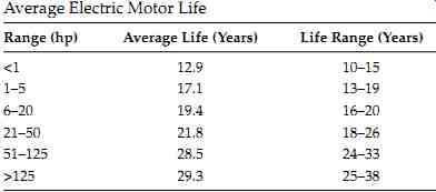
TABLE 11 Average Electric Motor Life Range (hp) Average Life (Years)
Life Range (Years)
The insulation system of a machine stator winding is complex and comprises of many insulating materials. The machine insulation system must be able to withstand continuous and transient stresses simultaneously imposed on it. These stresses are electrical, thermal, mechanical, and environmental and these stresses gradually degrade the insulation over its life. The electrical stresses can be dielectric aging, tracking, corona, poor connections, and transients (surges). The thermal stresses are aging, voltage unbalance and variations, cycling, loading, lack of ventilation, and excessive ambient temperature. The mechanical stresses are coil movement, rotor strikes, defective rotor, flying objects, and lugging of leads. The environmental stresses are moisture, chemical spills, abrasion, damaged parts, and restricted ventilation.
The effect of these stresses lead to degradation and failure of the stator windings that can be classified as failure modes. The reader should refer to Section 10.9 for additional information and inspection for evaluating the condition of machine insulation. The failure modes are discussed under each category of stress.
Electrical failure modes: Machine stator windings are exposed to surges that are due to lightning, ground faults, inductive load switching, closing of breakers under out of phase conditions, and variable speed drives (VFDs). The voltage between turns under normal operating conditions is relatively low (usually <100 V). Repetitive voltage surges gradually deteriorate turn-to-turn insulation, groundwall insulation, and semi-conductive and grading coatings. Surges produced by VFDs and other sources can create voltage transient with very fast rise times that can generate frequencies in the megahertz range. The high frequencies in the stator cause nonlinear distribution of voltage with a much greater percentage of the voltage appearing across the turn in the first coil connected to the phase terminal. The end result is that a very large voltage (as much as 40% of surge voltage) is impressed across the first turn. This voltage can be as high as several kilovolts across the turn insulation for a short time. The high voltage gives rise to partial discharges in the voids in the vicinity of the copper turns.
Random-wound stators with magnetic wire are very susceptible to this mode of failure. Also, VFDs can create high-voltage surges due to voltage reflections between the power cable and the motor surge impedance. This phenomenon also can lead to partial discharges that can degrade the ground and phase insulation. Electrical tracking is the formation of carbonized (conductive) path over the insulation surface in the end winding region of the stator. Tracking can result due to contaminated surfaces that enable the current to flow on the surface of the insulation of the end windings. These conductive regions will pick up capacitive charge from the high-voltage windings of the machine. Consequently, leakage current will begin to flow in the conductive paths on adjacent paths or from these paths to the core with sparking at the surface discontinuities. The sparking currents degrade the insulation and create conductive carbonized paths to ground and between phases. This failure mode causes the groundwall and/or phase insulation to fail. Another failure mode can be attributed to air pockets within the stator insulation. These air pockets are formed during make up of formed coils and/or installation of coils in the stator slots. Also excessive heating will degrade the organic insulation and it will delaminate creating air pockets within the groundwall insulation. The dielectric strength of the insulation with air pockets will be reduced by as much as a four factor to that of air.
If the voltage is high enough, the electric stress across the void will be high and a spark will occur in the void since the breakdown voltage of the air is much lower than the breakdown voltage of the solid insulation. This phenomenon is known as partial discharging in the voids and is stopped by groundwall insulation. However, repeated sparking will gradually break down the groundwall insulation. Many electrical connections are required for the coils and windings in the construction of a typical machine stator winding. Generally, form-wound stator insulation tends to have more voids than the random-wound stator insulation, and therefore is more susceptible to partial discharges. If the connections are made poorly the resistance of these connection will be high that will lead to overheating of the joints which then can degrade the insulation. Form-wound stator windings are more susceptible to this phenomenon since there are more joints that are required between coils and bars. However, any stator windings can have this problem that can eventually lead to failure of the machine.
Thermal failure modes: Thermal stresses are evidenced by looseness of the windings, adhesion of insulating materials and components, and loss of resistance to moisture. The I^2R losses (load losses) and eddy current losses in the windings, the stator core losses and the dielectric losses in the groundwall insulation give rise to the temperature of the copper conductors, core, and insulation. However, the temperature at the strand insulation is higher than the groundwall insulation. The temperature of stator windings can be higher than normal for several reasons. The temperature of air circulating to cool the machine increases above normal because of clogged plugged filters, air ducts, or heat exchanger problems. Another reason for the increase in winding temperature could be due to overloading the motor, or too frequent starting without allowing sufficient time between starts to allow the windings to cool down. Negative sequence currents in the will flow in the windings due to unbalance supply voltages to a machine.
The negative currents create an opposing torque which the machine has to over come by increasing current in the windings. Therefore, the negative sequence currents cause additional heating in the winding. Similarly, single phasing (loss of a phase) in the power supply to the motor can cause increase in current by as much as 200% of rated phase current. The continuous overheating can result in failure of the interstrand and strand-to-groundwall bonds because the strength of the bonds (both thermoplastic and thermosetting) decreases as the tempera ture increases. As the bonds fail, individual copper strands become loose.
Thermal and magnetic forces in the machine windings cause the strands movement resulting in abrasion of the strand insulation and reduced heat transfer between the conductors and groundwall insulation. This process leads to turn to-turn failures due to insulation abrasions or mechanical failure. Also, continuous operation at elevated temperatures will cause the epoxy and polyester to become brittle and shrink somewhat. The embrittlement and shrinkage will cause abrasions and cracking of the groundwall insulation during machine starting. The machine operation at the high temperatures will similarly cause the end winding blocking and bracing to slowly shrink and become brittle.
During motor starting, the looseness can then lead to movement of the coils causing abrasion and/or cracking of the insulation. Another failure mode can be attributed to thermal cycling by starting motors too frequently. Because of different coefficient of thermal expansion for copper and insulation materials, the difference in expansion between these materials creates shear stress. As a result of weakened strength of bond materials due to higher operating temperatures, the bond between the copper and the groundwall is lost creating gaps and delamination in the insulation. Thermal cycling can also weaken the bonds between the coils and the blocking and bracing in the end-winding. This will cause components to become loose and lead to abrasion of the insulation.
Mechanical failure modes: Mechanical forces in the stator windings are generated by currents flowing in the magnetic circuit of the machine stator, and from thermal expansion due to normal load currents. Magnetic forces are produced in the stator coils from the interaction of the rotor poles and stator slots which will tend to move the coils. This electromagnetic phenomenon occurs at twice normal frequency and is referred to as 120 Hz vibrations. The force produced by the above phenomenon is proportional to the square of the current. The mechanical forces are more pronounced in coils that are near the surface of the stator, i.e., adjacent to the air gap. Also, additional mechanical forces are generated between adjacent coils as a result of current flowing in each coil. Form-wound stator windings using thermoset insulation system are more susceptible to these cyclic forces because they are less flexible and it is more difficult to ensure that the coils are tightly wedged in the slots. Stator windings using thermoplastic insulation system are less susceptible to this phenomenon because the insulation is more flexible and tends to restrict coil movement by swelling and flowing to fill the slot. The conductor and groundwall insulation are cyclically stressed by compression and flexing because of coil movement resulting from these forces. The insulation may be damaged by the relative movement of strands and/or coils in the slots. The normal 60 Hz current flowing through the stator coils and bars creates magnetic forces at the rate of 120 Hz that causes relative movement between coils and/or bracing points in the end windings. If the end windings are not secured adequately they will rub against each other which will gradually abrade the insulation and lead to eventual failure. This failure mode also cause cracking of groundwall insulation which can lead to a ground fault, or abrasion of strand and conductor insulation resulting in turn-to-turn faults, or loss of semiconducting coating (if present) due to abrasions in the groundwall insulation, thus leading to partial discharges that can fail the groundwall insulation.
Environmental failure modes: The life of the machine winding insulation is dependent upon the environment in which it operates. The major environmental factors that can lead to a failure of the insulation were previously listed as moisture, chemicals, abrasive particles, contamination, and restricted ventilation. If there is excessive moisture, contamination (dust, dirt, and oil) combined with chemicals on the windings, and particularly on the end windings, can lead to electrical tracking or loss of insulation resistance and dielectric strength. The tracking failure mode was discussed under electrical failure modes. The loss of insulation resistance can lead to increased leakage currents in the insulation that will translate into higher temperatures. The higher temperatures in turn will lead to lower insulation resistance and so on. This phenomenon is self perpetuating and if allowed to continue will cause machine failure. Similarly, the combination of moisture, dust, and other contaminants degrade the insulation's mechanical and electrical properties. As a result of this contamination, the dielectric strength of the insulation system is reduced and thereby making it susceptible to failure by switching surges as was discussed under electrical failure modes. Another environmental factor is ambient that has significance for machines that are cooled by ambient air only. As the ambient temperature increases above the rated machine design ambient temperature, so will the winding temperature. If the total resulting temperature (ambient plus rise) is higher than the insulation rated temperature, it will degrade the insulation and failure may occur as was discussed under thermal failure modes. Abrasive particles in the cooling air (or closed cooling system) can cause erosion from impingement of the stator winding insulation. This problem is most likely to occur on open ventilated machines installed in dirty and abrasive environments. The insulation degradation from abrasive particles (dirty environment) can lead to interturn, ground or phase-to-phase faults. Chemicals can deteriorate the insulation if the insulation is exposed to acids, alkalis, paints, solvents, and the like. In some industries motors operate in such environments and therefore are susceptible to chemical attacks. This problem can also occur if the machine was cleaned with chemicals that are not combatable with the machine insulation system. Some older insulation systems using asphalt, varnish, and early polyesters as bonding agents are prone to softening, swelling, and loss of mechanical and electrical strength from exposure to certain chemicals. Modern stator windings insulation systems are less prone to chemical attacks. The most important means of preventing winding failure by this mechanism are to use totally enclosed machine, oil and grease leaks are contained, and that correct chemicals are used in cleaning of the windings. TABLE 12 summarizes the failure modes, aging stressors, and effects of machines.
==========
TABLE 12 Failure Modes, Aging Stressors, and Effects of Machines
Component Material Stressors Failure Modes Effects
Insulation Thermoplastic Asphaltic-mica, micafolium Thermal: at temperatures above 100°C causes delamination, slackness tape migration, reduced thermal conductivity Groundwall puffiness, high internal partial discharges, high winding temperature Strand and turn shorts due to movement of groundwall, puncture due to discharge and abrasion Thermosetting Epoxy mica, polyester mica Thermal: high temperature causes reduction in physical strength, shrinkage, reduced thermal conductivity Slackness in slot, high winding temperature, insulation embrittlement, discoloring of strand insulation Leads to slot discharge, puncture due to discharge and abrasion Groundwall insulation Epoxy mica, polyester mica, main air cooled machines Partial discharges due to looseness and abrasion of semicond. and insulation; poor semicond. application or grounding High partial discharges between core and winding (slot discharge), high semicond. resistance Electrical puncture due to reduction in groundwall insulation End winding discharge All types High dielectric stress at the surface of the end winding Reduced insulation resistance, high partial discharges Erosion of insulation by discharges, electrical tracking leading to puncture Windings All types, especially polyester mica Moisture Reduce electrical and mechanical strength of insulation, higher loss factor Higher losses leading to puncture; increased sensitivity to mechanical vibration All types of open machines Abrasive material attack Erodes insulation thickness Puncture due to reduced wall thickness and loosing of windings All types but especially motors High mechanical stresses Loose bracing and blocking, broken ties in end windings Abrasion of insulation and puncture
All types, especially polyester mica 120 Hz vibrations Causes vibrations between the winding and the slot, or at blocking points in end windings, resulting in insulation abrasion Phase-phase or phase-ground puncture due to partial discharges because of reduced insulation wall; also, turn insulation failure possible All types, but thermoplastic most sensitive Delamination discharge Partial discharge within groundwall make void larger due to original voids impregnated poorly, thermal cycling or operation at high temperature Groundwall puncture, turn-to-turn short All types, but especially motors with VFDs Steep front surges (fast rise dv/dt) causes high stress due to switching of starters and VFDs Surges can be as high as 5 PU of motor voltage rating, and last 0.1-1 µs cause High stress in interturn insulation Turn-turn-to-turn short, phase-phase or phase-ground failure especially in the first turns Girth cracking Primarily asphaltic and micafolium Thermal cycling causing tape separation, relative movement between winding and groundwall High internal partial discharge, loosening of end winding blocking and bracing Cracking of insulation just outside the slot, leading to puncture
===