AMAZON multi-meters discounts AMAZON oscilloscope discounts
.All electrical circuits use insulation which is suppose to be nonconductive and confines and guides the electric current to the inside of the circuit.
Therefore, the electrical insulation materials should exhibit (1) high resistance to the flow of electrical current, (2) high strength to withstand electrical stress, and (3) excellent heat-conducting properties. There are three fundamental electrical circuits and they are (1) the electric circuit, (2) the dielectric circuit, and (3) the magnetic circuit. These three circuits are analogous in many respects and are all governed by Ohm's law. For example, each of the three circuits can be written as follows:
The electric circuit is I= E / R
The dielectric circuit is psi = E / S
The magnetic circuit is phi = F / R
…where…
E is the electromotive force
F is the magnetic motive force
R is the electrical resistance
S is the dielectric resistance
R is the magnetic resistance (reluctance)
I is the current in the electrical circuit
psi is the electrical flux in the dielectric circuit
F is the magnetic flux in the magnetic circuit
Correspondingly, the formulas for electrical, dielectric, and magnetic resistance are also similar; that is:
r (1/ )( / ) SeLA =
r (1/ )( / ) RuLA
…where…
= (/) RLA r
where…
rho is the resistivity
e_r is the relative capacitivity (dielectric constant)
u_r is the relative permeability
Although these circuits are analogous to one another, they differ in actual practice. In the electrical circuit, the circuit is confined to the inside of the conductor and its path is along the conductor, where as in the dielectric and magnetic circuits the length of the path is short, irregular, and there is a large proportion of leakage flux usually into the air. In practice, it is much more difficult to make precise calculations for the dielectric and magnetic circuits than it is for the electric circuits. Furthermore, the current in the electric circuit can be measured very readily where as it is much more difficult to make similar measurements in the dielectric and magnetic circuits. In particular, the dielectric circuit differs further from an electric and magnetic circuit is in its design, predictability, and reliability. The dielectric circuit involves several terms and parameters that need to be understood in order to assess the characteristics and performance of the dielectric circuit. These terms are discussed as follows:
Dielectric: Dielectric is a term used to identify a medium, such as insulation in which an electric field charge can be produced and maintained. The energy required to charge the dielectric is recover able, in whole or in part, when the charge is removed.
Dielectric constant: Dielectric constant is known as specific inductive capacitance, capacitivity, or permittivity. The dielectric constant of any medium or material is defined as the ratio of the capacitance of a given configuration of electrodes with the medium as a dielectric, to the capacitance of the same configuration with a vacuum (or air) as the dielectric between the electrodes.
Dielectric absorption: Dielectric absorption is a phenomenon which occurs in dielectrics whereby positive and negative charges are separated to respective polarity when a DC voltage is applied to the dielectric. This phenomenon is time-dependent and usually manifests itself as a gradually decreasing current with time after application of DC voltage.
Dielectric loss: Dielectric loss is the time rate at which electric energy is transformed into heat in a dielectric when it is subjected to an electric field. Dielectric loss is associated with real component (watts) losses in a dielectric.
Dielectric PF: The dielectric PF of a material is the ratio of the power dissipated in the material in watts (watt loss) to the effective volt amperes (effective voltage × current) when tested with sinusoidal (AC) voltage. Numerically, it is expressed as a cosine of the dielectric phase angle (q) or cos q.
Dielectric DF: The dielectric DF is the tangent of the loss angle (90 - q). It is commonly referred to as tan d (tan delta).
Dielectric loss factor or dielectric loss index: The dielectric loss factor of any material is the product of its dielectric constant and its DF.
Dielectric strength: The dielectric strength of a material is the potential gradient (voltage) at which breakdown (electrical failure) occurs and is a function of the material thickness and its electrical properties.
Voltage gradient: A voltage gradient is defined as the electrical intensity at a point in an electric field, that is, force exerted on unit charge at a point. Numerically, it is equal to the density of the electric flux divided by the dielectric constant.
__6.1 Characteristics of Dielectrics (Insulation)
Dielectrics (insulation) for electrical equipment and apparatus is used for many different applications. It is expressed for a wide range of environmental conditions such as temperature, moisture, chemicals, other contaminants, and exposure to weather. One major factor affecting insulation life is thermal degradation, although moisture, contamination, voltage stress, and other factors may also contribute to its degradation. In addition, the life of an insulating material depends on the degree of loading, the type of service to which the equipment is subjected, the care it receives during installation and operation, and mechanical vibration and forces to which it is subjected.
The properties of insulating materials that are necessary and desirable are surface leakage, resistance to moisture, chemicals, oils and other contaminants, and mechanical properties. The important electrical characteristics of insulation are volume resistivity, PF, DF, capacitivity, dielectric constant, and dielectric strength. These characteristics, except for dielectric strength, can be assessed by nondestructive testing. These tests are:
- 1. AC dielectric loss
- 2. PF or DF (tan d )
- 3. Capacitance
- 4. AC resistance
- 5. Radio interference voltage (RIV)
- 6. DC insulation resistance
- 7. DC dielectric absorption
__6.1.1 Dielectric Loss
All solid and liquid insulations have some measurable loss since there is no perfect insulator. These losses are usually very small in the insulations typically used in electrical equipment and apparatus, and these losses vary as the square of the applied voltage. Gaseous insulations, such as air, do not have a measurable loss until they become overstressed or ionized. Dielectric loss is measured in watts (resistive components) and is a measure of energy dissipation through and over the surface of the insulation. The dielectric losses of most insulations increases with increase in temperature, moisture, and corona. Insulations may fail due to the cumulative effect of temperature, that is, rise in temperature causes an increase in dielectric loss which in turn results in a further rise in temperature. This phenomenon is self-perpetuating and continues until the insulation fails.
__6.1.2 PF and DF
The PF of insulation is defined as the ratio of watt loss to total charging volt-amperes, or the cosine of the angle q between total current vector (IT) and the impressed voltage vector. It is a measure of the energy component (resistive component) of the charging current. The DF is defined as the ratio of the watt loss to charging amperes, or the tangent of the angle d between the total current vector and the capacitive current vector. The angle d is the complementary angle of the PF angle q. Although, the charging volt- amperes and watt loss increase as the volume of insulation being tested increases at a given test voltage, the ratio of watt loss to the volt-amperes (PF or DF) remains the same regardless of the volume of insulation tested. Therefore, the basic relationship of PF or DF eliminates the effect of the volume of insulation-that is, the size of the electrical equipment or apparatus tested. This simplifies the problem of establishing normal insulation values for most types of electrical equipment. PF and DF testing is discussed in greater detail in Sect. 3.
__6.1.3 Capacitance
In a capacitor, the charge Q (amount of electricity) is proportional to the volt age E. The expression for this relationship can be written as:
Q = CE
...where C is a constant called capacitance. The capacitance of any electrical equipment, including capacitors, may be calculated from their geometry.
A capacitor in its most simple form is the parallel-electrode air capacitor as shown in FIG. 6a. The capacitance of such a capacitor can be calculated by the following formula:
C = KA / d
…where
A is the area between the electrodes
d is the thickness of the insulation (spacing between the electrodes)
K is the dielectric constant of the insulation (air).
The dielectric constant (K) of air is practically unity and the dielectric constant of the other insulation materials is defined in terms of air or vacuum.
TABLE 1 gives the dielectric constant values for most common types of insulating materials.
In cases where the geometry of the electrical equipment is simple and known, capacitance can be calculated mathematically. In the majority of cases, however, most insulation's geometry is usually too complex and not well-enough understood to derive a reliable calculation of capacitance mathematically.
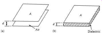 FIG. 6 (a) Parallel-plate air capacitor and (b) parallel-plate capacitor
with dielectric material.
FIG. 6 (a) Parallel-plate air capacitor and (b) parallel-plate capacitor
with dielectric material.
===
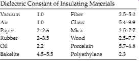
TABLE 1 Dielectric Constant of Insulating Materials
- Vacuum 1.0 Fiber 2.5-5.0
- Air 1.0 Glass 5.4-9.9
- Paper 2-2.6 Mica 2.5-7.7
- Rubber 2-3.5 Wood 2.5-7.7
- Oil 2.2 Porcelain 5.7-6.8
- Bakelite 4.5-5.5 Polyethylene 2.3
===
__6.2 Insulation as a Capacitor
A perfect insulator can be represented by an ideal capacitor as shown in FIG. 7a. However, all electrical equipment insulation have losses and therefore an insulator is not a pure capacitor. Thus, the electrical circuit of a practical insulator can be represented by a capacitor with a small resistance in parallel with it, as shown in FIG. 7b.
The nature of insulation materials is such that 60 Hz current does not easily flow through them and therefore their purpose is to guide the current to the inside of the conductor. When voltage is applied to the conductor, two fields are established; one due to the current flow (magnetic field) and the other due to the voltage (dielectric or electrostatic field). The lines of magnetic flux around the conductor are concentric circles, whereas the lines of the dielectric flux around the conductor are radial. The resulting voltage stress due to the dielectric field varies inversely with the distance between equipotential lines.
The dielectric constant of an insulator is an indication of how much dielectric flux the insulation will allow through it. Under identical conditions insulation with a higher dielectric constant will pass more dielectric flux through it than another insulation having a lower dielectric constant. The dielectric constant for most commercial insulations varies from 2.0 to 7.0 as indicated in TABLE 1. It should be noted that the dielectric constant of water is 81 and generally when insulation becomes wet, its dielectric constant increases along with its capacitance, thus resulting in greater dielectric loss. An ideal insulation can be represented as a capacitor because its behavior is similar to that of a capacitor. Two of the most common configurations considered for insulators are parallel-plate and cylindrical capacitors. For example, the parallel-plate capacitor represents an insulation system of a transformer or a machine winding, whereas the cylindrical capacitor represents an insulation system of a cable or a bushing.
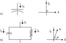
FIG. 7 Electrical representation of insulation: (a) perfect and (b) practical.
__6.3 DC Voltage versus AC Voltage Tests
When voltage is applied to the insulation, a current is established consisting of a charging current (IC) and an in-phase component current (IR). As shown in FIG. 7b, the charging current leads the in-phase component current by 90°. The vector sum of the charging current and the in-phase component current is the total current (IT) drawn by the insulation specimen. The in-phase component current is also referred to as the resistive current, loss current, or conduction current. The ideal insulation (ideal capacitor) behaves some what differently under the application of DC versus AC voltages which are discussed below.
__6.3.1 DC Voltage Tests
When a DC voltage is applied to the insulation, a large current is drawn at the beginning to provide the charging energy, however, this current decreases to a minimum level over time. The minimum current is due to continuous leakage or watt loss through the insulation. The energy required to charge an insulation is known as the dielectric absorption phenomenon.
In actual practice, the losses from dielectric absorption (i.e., the absorption current) are much higher than the continuous leakage losses. In the case of DC voltage testing, the effect of dielectric absorption becomes minimum over time and therefore measurements of continuous leakage current can be made.
Dielectric absorption losses are very sensitive to changes in moisture content of an insulation, as well as the presence of other contaminants. Small increases in moisture content of an insulation cause a large increase in dielectric absorption. The fact that dielectric losses are due to dielectric absorption makes the dielectric loss, PF, or DF test a very sensitive test for detecting moisture in the insulation. When a DC voltage is applied to an insulation, the total current drawn by the insulation is comprised of capacitance charging current, dielectric absorption current, and continuous leakage currents. These currents and their behavior are discussed in greater detail in Sect. 2.
__6.3.2 AC Voltage Tests
In the case of AC voltage application to an insulation, a large current is drawn which remains constant as the AC current alternately charges and discharges the insulation. The effect of dielectric absorption currents remains high because the dielectric field never becomes fully established due to the polarity of the current reversing each half cycle. When an AC voltage is applied to an insulation, the currents drawn by the insulation are due to capacitance charging, dielectric absorption, continuous leakage current, and corona which are discussed below:
Capacitance charging current: In the case of AC voltage, this current is constant and is a function of voltage, the dielectric constant of the insulating material, and the geometry of the insulation.
Dielectric absorption current: When an electric field is set up across an insulation, the dipole molecules try to align with the field. Since the molecules in an AC field are continually reversing and never fully align, the energy required is a function of material, contamination, (such as water), and electrical frequency. It is not a function of time.
Leakage current (conductivity): All insulation materials will conduct some current. If voltage is increased beyond a certain level, electrons will be knocked off of molecules causing current to pass through the insulation. This is a function of the material, contamination (especially water), and temperature. Excessive conductivity will generate heat causing the insulation to cascade into failure.
Corona (ionization current): Corona is the process by which neutral molecules of air disassociate to form positively and negatively charged ions. This occurs due to overstressing of an air void in the insulation.
Air voids in oil or solid insulations may be due to deterioration from heat or physical stress, poor manufacture, faulty installation, or improper operation. Corona breaks down the air into ozone which, in combination with water, forms nitrous acid. The ionized air bombards the surrounding insulation and causes heat. The combination of these conditions will result in deterioration of the insulation and carbon tracking. Corona losses increase exponentially as voltage increases.
__6.4 Insulation Breakdown Modes
Insulation breakdown can be classified as (1) failure due to excessive dielectric loss and (2) failure due to overpotential stress. These failure modes are discussed below:
Excessive dielectric loss is the result of deteriorated insulation or the contamination of the insulation with a poor dielectric such as water. As the dielectric losses increase, the temperature of the insulation increases resulting in even greater dielectric loss. Over time, the phenomenon eventually results in complete failure of the insulation. Overpotential stress occurs when a voltage is applied across an insulation greater than its dielectric strength. The molecular forces are overwhelmed and the insulation becomes a conductor. Some of the causes of insulation failure due to overpotential stress are (1) external increase in applied voltage, (2) decrease of insulation thickness, and (3) air bubbles or pockets in the insulation.
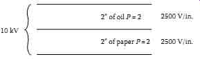
FIG. 8 Insulation system rated for 10 kV.
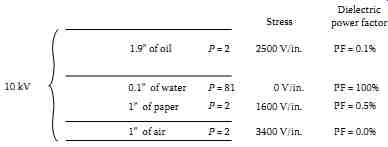
FIG. 9 Insulation system with water and air contamination.
Example of insulation failure
Let us take an example of an oil-filled transformer that has oil and solid paper as an insulation system. For the purposes of this example, let us assume that this insulation system has 2 in. of oil and 2 in. of paper insulation. Since the dielectric constant for both paper and oil is 2.0, we can assume that each insulation system can withstand 2500 V/in., giving a total voltage withstand capacity of 10 kV as shown in FIG. 8.
In order to put contamination in this insulation, let us replace one-tenth (1/10) inch of the oil with water and 1 in. of paper insulation with air (i.e., by putting voids in the paper as shown in FIG. 9). Therefore, with the added contamination, the 10 kV rated insulation system is now rated at 9.750 kV assuming that the air voids do not break down. Since air has a lower dielectric constant, it will take more high-voltage stress than paper as shown in FIG. 9. In this example, the two failure modes may be described in the following manner:
Failure due to excessive dielectric loss: The contamination of the oil insulation with water increases the dielectric losses in the oil and simultaneously reduces the dielectric strength of the insulation.
Because of increased losses in the oil insulation over time, it will become degraded and eventually fail.
Failure due to overpotential stress: This failure mode occurs when air is introduced into the insulation. Air, although a good dielectric at low voltages becomes overstressed at higher voltages. It is assumed, in this example, that the air voids become overstressed at 2500 V and begin ionizing, thus resulting in corona which will eventually deteriorate the paper insulation. In this mode, the reduced thickness of the insulation and the resulting voltage overstress causes the insulation to fail.