AMAZON multi-meters discounts AMAZON oscilloscope discounts
3 Origins of PQ Problems and Harmonics
Power disturbances can originate from many sources external and internal to a facility's electrical power distribution system. External sources are:
Power system faults
• Lightning
• Switching
• Surges
• Accidents involving electric power lines and feeders
• Examples of internal sources are Line and capacitor switching
• Motor starting or switching of large inductive loads
• Harmonic producing loads (linear and nonlinear (solid-state and electronic) loads)
The mechanisms involved in generating electrical disturbances often deter mine whether occurrence of disturbances is random or repeatable, unpredictable, or easy to find. Untrained users often attribute power disturbances to the utility source.
A brief description of some of the major sources of power disturbances follows:
Power system faults: Power system faults can cause a momentary voltage reduction to a complete loss of power lasting for a few cycles, seconds, minutes, hours, or days. Power system faults may be classified as temporary or permanent. Usually the temporary faults are confined to overhead distribution lines where a line may suffer a momentary fault which will open the circuit breaker. However, the circuit breaker will reclose immediately to restore the circuit. Permanent faults are confined usually to underground feeders. Due to their location, the detection and repair of these types of faults require a considerable amount of time. Also, the power system faults may result from power apparatus failure such as transformers, circuit breakers, etc. which require a longer time to repair or replace.
Lightning surges: Direct lightning strikes to the power system conductors cause overvoltages near their points of impact. Direct hits inject the total lightning surge into the system. As a result, current amplitudes can range from a few thousand amperes to a few hundred thousand amperes. The rapid change of current through the impedance of the conductors produces a high voltage drop, which causes secondary flashover to ground. This diverts current even in the absence of an intentional diverter. Lightning strikes also can activate lightning arrestors and/or surge arrestors. A flash over of line insulators can trip a breaker, with reclosing delayed by several cycles, causing a power interruption. The power system also can be affected indirectly by lightning. These effects include overvoltages in conductors and ground potential rises in grounding grids or the earth.
Load switching and surges: Load switching forms a transient disturbance whenever a circuit containing capacitance and inductance, such as capacitors, starting motors, or switching feeders, is switched on or off. In these circuits, the currents and voltages don’t reach their final value instantaneously. The severity of such disturbances depends on the power level of the load being switched and on the available short-circuit current of the power system. Switching large loads on or off can produce long-duration voltage changes beyond the immediate transient response of the circuit. More complex switching can produce surge voltages reaching 10 times the normal circuit voltages, involving energy levels determined by the power rating of the elements being switched. Also, energizing loads, such as large motors, may cause voltage dip that can affect operation of microprocessor-based equipment.
Linear and nonlinear loads: The power system harmonic problem is an old problem and, in many instances in the past, we have been able to go around it and reduce its effects. The harmonic producing linear loads are devices such as transformers, generators, motors, electromagnetic ballasts, and saturated magnetic devices that have been around a long time. These are discussed in more detail in Section 12.4. The nonlinear loads are generally classified as those devices that are electronic and solid-state devices used in power conversion and control. It’s clear that nonlinear loads draw nonsinusoidal currents from the power system, even if the power system has a perfect sinusoidal waveshape. These currents produce nonsinusoidal voltage drops in the system's source impedance which distorts the sine wave produced by the power source. A typical nonlinear load is a direct current (DC) power supply with capacitor-input filter. They are used in most computers and draw current only at the peaks of the voltage sine wave. Nonlinear loads typically result in harmonic distortions (HDs) in the power system. These loads can be broadly classified into four categories as follows.
1. Power electronic devices: Power electronic devices are being employed in small appliances to huge converters on the transmission system. Typical applications of power electronics include switch-mode power supplies (SMPS), adjustable speed drives (ASDs), electronic ballasts, and the like.
2. Saturatable devices: Most saturatable devices are transformers which generate harmonics due to the nonlinearity of the transformer excitation. These harmonics are small unless the transformer is overexcited due to high voltage magnitudes.
3. Arcing devices: Arcing devices are used most commonly in fluorescent, high and low pressure sodium and mercury-vapor lamps.
Other types of these devices include arc furnaces or arc welders.
4. Electrostatic discharges (ESDs): An ESD buildup results from a rubbing action between two materials (solid or liquid) of different surface energy characteristics. This is due to an absence of a conductive path between the two materials. The ESD is quickly released when a conductive path (discharge arc) is established. Such discharges can be harmful to semiconductor devices in sensitive electronic equipment. Discharge voltages often range from 5 to 40 kV.
Grounding design and installation: Improperly grounded systems which have multiple ground points are common causes of PQ disturbances. Grounding systems which don’t have sufficiently low ground impedance don’t allow the proper amount of current flow necessary for the operation of the circuit protection devices, thereby compromising the safety of personnel and equipment. Such systems also cause failures in electronic equipment due to leakage currents. Leakage currents created by power line noise, coupled with high-ground impedances, cause voltage to develop on the ground conductor that can trigger a failure in electronic equipment. A ground system with multi ground points can create multi-ground loops and impose stray currents on the logic chips of microprocessors. Therefore, it’s essential that the design and installation of earth grounds and equipment grounds should be done carefully.
Since the ground system also serves as an equal potential reference between peripherals, an improperly designed ground can affect microprocessor logic and inject unwanted signals. The logic circuitry of a microprocessor uses the ground system as a zero conductor. See Section 12.7 for a more detailed discussion on grounding design and installation.
Wiring design and installation:
Wiring design and installation problems can be classified as follows:
1. Problems involving the hot, neutral, and ground wires
2. Missing connections, improper connections, loose connections, open grounds, N-G shorts, two hot wires in an outlet, reversed polarity
3. Lack of an isolated ground (IG) receptacle when called for
Because microprocessors use the ground wire as the zero-voltage reference, stray currents imposed upon it can change information and damage microprocessor components. Additional power distribution problems can occur because many pieces of equipment typically are connected together through the building's grounding system, including conduit or data cables. If the ground paths of individual pieces of equipment are not isolated from one another, currents carried on one can affect another's operation. When a piece of equipment is plugged into a standard wall receptacle without an IG designation, its ground wire is immediately connected to every other piece of equipment in the building by means of building conduit. This is similar to the manner in which a large radio antenna picks up radio signals it was never meant to receive. Data cables are extremely sensitive to such cross talk.
4 Characteristics of Typical Linear and Nonlinear Loads
The harmonic loads may be classified as linear and nonlinear loads. The linear loads that produce harmonics are iron core devices which operate in the nonlinear (saturated) region of the iron core. Also, depending on the winding pitch, motors and generators may produce harmonics. These sources (loads) have been around since the early days of power systems, but the harmonics produced by these devices have been manageable. The traditional (established) sources of harmonics include the following:
Tooth ripple or ripples in the waveform arising from the rapid pulsations and oscillations of the field flux caused by movement of the poles in front of the projecting armature teeth cause harmonic output. This tooth ripple causes flux distortion in synchronous machines.
Variations in air gap reluctance over the synchronous machine pole pitch set up a continuous variation in flux, which permeates to the waveshape, and leaves harmonics as a result.
Flux distortion in the synchronous machine may be due to load effects.
• Sharp variations in the load result in sudden changes in machine speed without changes in flux, thus setting up a distorted waveshape.
Generation of nonsinusoidal emf's are due to nonsinusoidal distribution of the flux in the air gap of synchronous machines.
Limited transformer current harmonics, primarily third harmonic, occur at no load.
Imposition of small and limited amount of nonsinusoidal currents, although input voltages are pure sine wave, occur in networks containing nonlinearity. Typical of these nonlinearities are welders, arc furnaces, voltage controllers, frequency converters, etc.
To a lesser extent, but of importance is the fact that a drastic change in the design philosophy of all power equipment and load equipment has taken place.
In the past, manufacturers tended towards underrating or overdesigning most equipment. Now, in order to be competitive, power devices and equipment must be critically designed. In the case of iron core devices, this means that the operating points are more into the nonlinear characteristics, resulting in a sharp rise in harmonics from the established power equipment and load equipment.
Today, however the application of electronic equipment continues to change the electrical environment in the power distribution system of most commercial and industrial facility. In the past, the most common loads found in electrical distribution systems were linear loads such as motors, incandescent lighting, and electric heating. Although these loads still exist in modern facilities, other loads-primarily electronic-that have nonlinear load characteristics represent a large percentage of the total load. Because of the proliferation of nonlinear loads, harmonic currents have increased significantly in electrical distribution systems. Since the electrical distribution systems in most facilities were designed to match the characteristics of linear loads (i.e., nearly sinusoidal waveforms), the application of nonlinear loads have caused serious problems such as overheating of conductors, transformers, inadvertent circuit breaker tripping, capacitor failures, and malfunction of electronic equipment. The nonlinear loads consume substantial amounts of energy and thus have a greater impact compared to the linear loads on a facility's electric power distribution system. Linear loads have an impedance characteristic which is basically constant over time with applied voltage. If a sinusoidal voltage is applied to these loads, the current drawn also is sinusoidal.
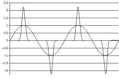
FIG. 10 Load current waveforms: sinusoidal load and rectified (nonsinusoidal)
load.
In contrast, nonlinear electronic loads don’t draw sinusoidal current. The applied power to these loads is either rectified by a diode bridge or the device is turned on and off with switching components such as SCRs, triacs, or transistors.
FIG. 10 shows the current waveforms of linear load (sinusoidal) and rectifier (SMPS) load. In FIG. 10, the sine waveform is representative of heaters, incandescent and motor type loads, the pulse waveform is representative of electronic loads that draw current in pulses (i.e., nonsinusoidal waveform), or draw current for the portion of each cycle by turning on and off. The nonsinusoidal loads don’t draw current for the entire cycle but rather draw current in small period per cycle or turn on at a specific point in the cycle. The current drawn by the electronic loads is in abrupt transitions which interact with system impedance causing voltage loss and transients (impulses).
Some electronic loads are constant power loads, such as SMPS, and for these loads a decrease in voltage within the operating range will cause an increase in current to maintain constant power. Also, the harmonic currents of the load interact with the impedance of the distribution system thereby causing harmonic voltage drops. When the distribution system impedance is high, the harmonic voltage drops are high and the harmonic currents for the nonsinusoidal loads are lower. When the distribution system impedance is low, the harmonic voltage drops are low and harmonic current for the non linear loads are high. The nonlinear loads when combined with high current inrush and high distribution system impedance tend to cause severe voltage dips and voltage waveform distortion. Under these conditions, the constant power electronic loads attempt to compensate by increasing current draw.
The increased current draw interacts with the impedance of the distribution system and adds to the voltage dip, and if the voltage dip is severe enough loads throughout the distribution system will crash. In addition to producing line voltage drops, the third harmonic currents (odd-order triplen harmonics) don’t cancel out and flow in the neutral circuit of a three-phase, four-wire system. As a result, these currents return back to the power source over the neutral conductor. These currents can be higher than the phase currents and, therefore, create new concerns over the adequacy of the neutral of the three-phase power supply system.
To cope with harmonics problems caused by nonlinear loads, load characteristics of system harmonics must be studied and understood. The load characteristics can, for the most part, be determined from an examination of the load response to a distorted voltage waveform at load terminals.
4.1 Voltage and Current Characteristics of Nonlinear Loads
4.1.1 HD Terminology
The nonsinusoidal periodic waveform of nonlinear loads can be represented through Fourier analysis as the sum of a DC component and sine waves of various amplitudes and phase displacement from some relative angle. The sine waves all have frequencies which are multiple of the fundamental frequency of 60 Hz. The voltage and current waveforms can then be represented as the sum of a DC component and sine waves with a fundamental frequency w1 as follows:
The voltage and current equations represent sine waves that are multiples of a fundamental frequency, and are called harmonics. The effective value (rms) of current waveform where the amplitude of each harmonics is known can be obtained by the equation as follows:
The nonlinearity (i.e., distortion) of the waveform can be determined in terms of THD, crest factor (CF), and form factor. The THD is defined as the ratio of the rms value of the total harmonic currents and the rms value of the fundamental current. The THD is expressed as a percentage of the fundamental current is given by the equation:
The CF is defined as the ratio of the peak of a waveform to its rms value and can be written as…
In a purely (i.e., linear) sinusoidal waveform the CF is equal to square root of 2 (i.e., 1/(0.707)), or 1.414. The form factor is defined as the ratio of the rms value of a waveform to rms value of the waveform's fundamental, and can be written as…
4.1.2 Types of Nonlinear Loads
Four types of nonlinear power electronic devices are increasingly being used in commercial facilities. These are fluorescent lighting, ASDs, SMPS, and uninterruptible power supplies (UPS). A brief description of voltage and current characteristics of each is detailed below.
Fluorescent lighting: Fluorescent lighting has overtaken incandescent lighting as the most popular and widely used lighting system. Light in fluorescent lamps is generated by gas discharge. The lamps require a ballast to provide proper starting and operating voltages and to limit current during lamp operation. Two types of ballasts are used with fluorescent lamps: magnetic core-coil and electronic. Both types generate harmonics. Magnetic ballasts generate third HD typically in the range of 13%-20%. In contrast, recent tests conducted by Lawrence Berkeley Laboratory show that HD generated by currently available electronic ballasts can vary from 5% to well over 33% of the fundamental current, depending on their design. In fact, some types of electronic ballasts generate less harmonic currents than magnetic ballasts.
Most manufacturers are holding HD to levels well below those recommended by ANSI (THD less than 32%). In summary, the THD of electronic ballast is comparable to magnetic ballasts, electronic ballast have wide range of individual harmonic currents, and use much less power than magnetic ballasts.
Variable frequency drives (VFDs): Most VFDs contain a front-end rectifier, DC link, and an inverter, operating together with a control system. The rectifier converts the three-phase AC input to DC voltage. Depending on the type of system, a reactor, a capacitor, or a combination of these are used to smooth the DC signal. The inverter circuit uses the DC voltage to create a variable frequency AC voltage to control the speed of the AC motor. The VFDs are also referred to as ASDs or variable speed drives (VSDs). The characteristic harmonics for a VFD or ASD are based on the number of rectifiers (pulse number) in a circuit and can be determined by the following:
h = (n × p) ± 1 where h is the harmonic order n is an integer (1, 2, 3, 4, 5, 6, …) p is the number of pulses of rectifier
For example, using the above equation, the six-pulse rectifier shown in FIG. 11a will create characteristic harmonics of 5th, 7th, 11th, 13th, 17th, 19th, and so on. The degree and magnitude of the harmonics is function of the drive design and the interrelationship of the nonlinear load with the connected distribution system impedance. The power source line impedance ahead of the controller will determine the magnitude and amplitude of harmonic currents and voltages reflected back into the distribution system as is shown in FIG. 11b. The distorted current reflected through the distribution impedance causes a voltage drop or harmonic voltage distortion. This relationship is proportional to the distribution system available fault current and to the distribution system impedance.
The two most commonly used AC drives are: voltage source inverter (VSI) drives and current source inverter (CSI) drives. Each is briefly described below.
VSI drives: VSI drives employ a large capacitor in the DC link to provide a relatively constant voltage to the inverter. The inverter then breaks up this DC voltage to provide the variable frequency AC voltage for the motor. Most inverter drives use pulse width modulation (PWM) techniques to improve the quality of the output voltage waveform. Typical applications of these drives are motors up to 100 hp.
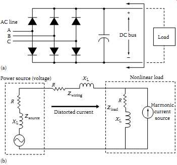
FIG. 11 (a) Six-pulse front-end converter for AC drive, and (b) its
equivalent circuit.
CSI drives: CSI drives are typically used for larger motor applications where custom design can be justified. The DC link consists of a large choke to keep the DC current relatively constant. The inverter then breaks up this current waveform to provide the variable frequency AC signal for the motor.
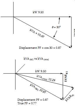
PF characteristics of VFDs also can be very important because the application of capacitors for PF correction can create special problems, including harmonic resonance and transient voltage magnification. The displacement component of the PF is associated with the angle between the voltage and the current.
Without any distortion, the PF is equal to the displacement PF (DPF). Both drives have distorted current waveforms, that adds a distortion component to the PF (true PF is real power divided by total apparent power).
The distortion, and therefore the PF, can be considerably worse for VSI-type drives than for most CSI-type drives. Phase-controlled CSI drives have a very poor PF if operated with large rectifier firing delay angles. Transient voltage withstand capability is another important characteristic of VFDs. Power semi conductor switches that have a peak inverse voltage (PIV) rating of only 1200 V are used in many VFDs. On a 480 V distribution system, this PIV rating equates to 177% of normal system voltage. In most power semiconductor switch assemblies, onboard metal-oxide varistors (MOVs) are utilized for protection purposes. While the MOVs are effective for many low energy transients, they can be destroyed by magnified capacitor switching transients if not sized correctly. Drive topology and the control system characteristics also affect the sensitivity of VFDs to transient disturbances. VSI-type drives require smoothing of the DC line voltage with a large capacitor for proper operation.
For protection of inverter components, the DC bus voltage is monitored and the drive is tripped when it exceeds a preset level. Momentary interruptions or voltage dip on the input voltage can affect drive controls as well. This characteristic is very dependent on the specific controls involved, but it’s not uncommon for voltage dips lasting only a few cycles to cause drives to trip.
SMPS: SMPS generate harmonics due to the switching action of the rectifier bridge which supplies the switching regulator. A DC capacitor provides an essentially constant DC voltage for the switching regulator. In order to maintain this DC voltage, the capacitor only needs to draw a pulse of current near the peak on each sine wave. The resulting current waveform is shown in FIG. 12. The power relationship based on sinusoidal voltage and cur rents won’t be valid with these waveforms. For one thing, the peak current is no longer 1.414 times the rms current. The CF (ratio of peak to rms) for this current is much higher and any meter, controls or relay which is sensitive to the peak current must take this into account. The current drawn by the SMPS contains significant harmonic components. FIG. 13 shows that the highest harmonic component is the third.
Harmonic components in this current also have a dramatic effect on the PF of the load. Although the 60 Hz component of the current (fundamental) is in phase with the voltage (DPF close to unity), the harmonic components reduce the true PF and indirectly reduce the real power available.
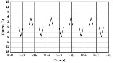
FIG. 12 Current waveform of SMPS. (Electrotek Concepts, Inc)
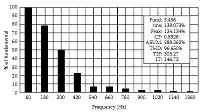
FIG. 13 Harmonic current of SMPS. ( Electrotek Concepts.)
4.1.3 PF Characteristics of Loads
PF is defined as the ratio of real power divided by the apparent (total) power, i.e., watts divided by volt-amps (VA). Resistive loads produce unity PF, however, all reactive (inductive and capacitive) loads produce non-unity (i.e., less than 1.0) PF. The PF for the linear and nonlinear loads is given by the following expressions:
1. Linear loads
Uncorrected electronic power supplies exhibit very poor true PF and high harmonics which generate heat in the phase and neutral wires of the electrical power distribution system, especially where single-phase 120 V power is supplied from a 208/120 V three-phase wiring system. The PF defines how efficiently a load utilizes the current that it draws from an AC power system.
The PF can also be expressed in terms distortion factor to give an assessment of the efficiency of the load utilization in the presence of harmonics. Therefore for a sinusoidal circuit (i.e., no harmonics), we can write voltage and current equations at the load as the following:
The true PFs calculated above represent maximum true PFs for nonlinear loads. Actual true PF is the product of maximum true PF and DPF, and the product can be significantly lower than DPF. The PF comparison shown above gives an optimistic picture because harmonic currents actually cause more losses per ampere than do fundamental currents.
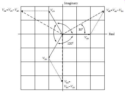
FIG. 15 Voltage phasors in a balanced three-phase system (phase sequence
abc).
4.1.4 Phase Sequence of Harmonics
In a balanced three-phase power system, the voltages and currents in phases a-b-c are shifted in time by ±120° of fundamental. Taking a-phase as a reference, we can write an equation for a-phase current as...
By examining the above current equations, we see that:
The first harmonic (i.e., the fundamental) is positive sequence (a-b-c) because phase b lags phase a by 120°, and phase c leads phase a by 120° (or lags phase a by 240°) The second harmonic is negative sequence (a-c-b) because phase b leads phase a by 120°, and phase c lags phase a by 120°
The third harmonic is zero sequence because all three phases have the same phase angle The pattern for a balanced system repeats and is shown below as "Phase sequence of harmonics in three-phase balanced system."
If a system is not balanced, then each harmonic can have positive, negative, and zero sequence components. However, in most cases, the pattern shown above can be assumed to be valid.
Because of Kirchhoff's current law, zero sequence currents cannot flow into a three-wire connection such as a delta transformer winding or a delta-connected load. In most cases, systems are fairly well balanced, so that it’s common to make the same assumption for third harmonics and other triplens. Thus, a delta grounded wye transformer at the service point of an industrial facility usually blocks the flow of triplen harmonic load currents into the power system.
Unfortunately, the transformer does nothing to block the flow of any other harmonics, such as fifth, seventh, and so on. Zero sequence currents flow through neutral or grounding paths. Positive and negative sequence currents sum to zero at neutral and grounding points. Another interesting observation can be made about zero sequence harmonics. Line-to-line voltages never have zero sequence components because, according to Kirchhoff's voltage law, they always sum to zero. For that reason, line-to-line voltages in commercial buildings are missing the third harmonic that dominates L-N voltage waveforms. Thus, the V THD of line-to-line voltages is often considerably less than for L-N voltages.
4.1.5 Harmonic Generating Characteristics
In the past, harmonic currents originated primarily from a few major sources, such as arc welders, fluorescent ballasts and lights, arc furnaces, etc. As explained previously, significant harmonics are being generated by today's load equipment such as switching power supplies, solid-state controls, and other sensitive electronic equipment. The harmonics in these nonlinear loads cause voltage distortion, poor PF, and stress on supply power system equipment. Harmonics from nonsinusoidal loads interact with electrical distribution system impedance, creating heat in electrical distribution equipment. Harmonic voltage distortion limits peak applied voltage and may increase susceptibility to momentary voltage dropouts.
4.1.6 Sensitivity to Harmonics
Most electronic equipment is affected by harmonics because high levels of harmonic currents cause problems in the power system that is not designed for nonlinear loads. The problems are:
Overloading of the phase and neutral conductors of the power distribution system
Overheating of the distribution transformers, where high-frequency currents can cause higher losses from eddy currents, magnetic hysteresis, and skin effect;
Overloading of power sources such as UPS systems and emergency generators including generator controls;
Poor utilization of available power from the branch circuits because of low PF;
Premature failure of PF correction capacitors because of overheating by harmonic currents;
Flat-topping of the voltage waveform caused by high-peak currents which reduce the ride-through capability of the electronic equipment
4.1.7 Sensitivity to Voltage Variation
All electronic equipment is generally sensitive to supply voltage variations. For example, computer systems can experience performance problems if the following voltage thresholds are exceeded: sags greater than -20% rms, spikes greater than 100% peak, and swells greater than +10% rms. When assessing the impact of voltage variation on electronic equipment, it’s helpful to know the related voltage waveforms, that is whether they are swell, sag, impulse, or electrical noise. The effects of power line voltage variation, resulting from a utility's power system disturbances or interaction of the load and its power source, may appear in many forms. Sensitive electronic equipment may cease to operate, errors may occur in processing and data transfer, or hardware damage may occur.
4.1.8 Sensitivity to Voltage Flicker
Voltage changes which are cyclical in nature (occur in the range of 0.5-30 Hz) are commonly referred to as voltage flicker. Voltage flicker can be caused by: repetitive motor starting, punch presses, large reciprocating compressors, resistance welders, and arc furnaces. Voltage flicker can affect the sensitive electronic load equipment, especially if it happens near peak voltage when the DC power supply usually draws AC line current.
4.1.9 Sensitivity to Noise
All power lines, motors, generators, and other current handling devices radiate magnetic fields of varying strengths (electric noise). In addition to the above sources of electrical noise, fault produced transients, surges, and ground potential rises also produce unwanted magnetic fields. The generated and radiated magnetic fields couple across to other cables (both power and communications) and affect sensitive electronic equipment. The level of electrical noise that is considered acceptable depends on the signal level and accuracy requirements of the load equipment. Separation of the electrical noise sources and load signal cables, proper grounding, and proper cable configuration are some of the techniques for reducing noise.
===
