AMAZON multi-meters discounts AMAZON oscilloscope discounts
__3. Selection of Grounding System
As discussed earlier, the various methods of grounding commonly used are solidly grounded, resistance grounded, reactance grounded, and ground fault neutralizer grounded. The ungrounded system, in the true sense of the word, is grounded, because the charging capacitance from the phase conductor to earth acts as the grounding point. The various grounding methods are shown in FIG. 7.
The selection of a grounding system should be based upon the following systems factors:
Magnitude of the fault current
Transient overvoltage
Lightning protection
Application of protective devices for selective ground fault protection
Types of load served, such as motors, generators, etc.
The application limits and a guide for the various grounding methods for consideration of the above-mentioned factors are shown in TBL. 1 and discussed in the following sections.
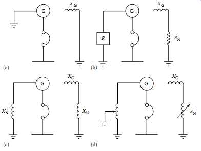
FIG. 7 Methods of grounding system neutrals. (a) Solidly grounded; (b)
resistance grounded; (c) reactance grounded; (d) ground-fault neutralizer.
=======
TBL. 1 Grounding Methods for Low- and Medium-Voltage Systems
System Grounding Practice Comments Medium-voltage system (2,400-13,800 V) Wye-connected generator on the system Use low-resistance grounding resistor Allows the use of neutral-type lightning arresters if X0/X1 = 3 X0/X1 = 10 for limiting transient overvoltages Wye-connected transformer on the system Use low-resistance grounding resistor R Does not allows the use of neutral-type lightning arresters To limit transient overvoltage, R0/X0 = 2 System ungrounded (i.e., no wye connected generators or transformer) Use grounding transformer with resistor Zig-zag transformer R Some comments as for wye-connected transformer Low-voltage system (120-600 V) Wye-connected generator on the system Use low-voltage reactance to ground generator neutral Ground fault current should be not less than 25% of three-phase fault current Wye-connected Transformer power supply system Ground transformer neutral solidly to ground; Ground fault current can be equal to three-phase fault current (or greater at the secondary of delta-wye-connected transformer) System ungrounded (i.e., no wye connected transformer) Use grounding transformer solidly grounded Zig-zag transformer Ground fault current to be equal to at lest 25% of three-phase fault current R G
=======
__3.1 Solidly Grounded System
A solidly grounded system is one in which a generator, transformer, or grounding transformer neutral is directly grounded to earth or station ground.
Because the reactance of source (generator or transformer) impedance is in series with the neutral circuit, this system cannot be considered a zero impedance circuit. In nearly all grounded systems, it’s desirable to have the line to ground fault current in the range of 25%-110% of three-phase fault current in order to prevent the development of high transient over voltage. The higher the ground fault current, the less are the transient overvoltages.
Ground-neutral-type lightning arresters may be applied on this system provided that the ground fault current is at least 60% of three-phase fault current. Another way of expressing this value is to express the reactance and resistance ratios as follows:
… where X0 is the zero-sequence reactance X1 is the positive-sequence reactance R0 is the zero-sequence resistance
Normally, direct grounding of the generator is not desirable because the ground fault current may exceed three-phase fault current. Since the generator is rated for maximum three-phase fault current, it’s not desirable to have higher ground fault currents than three-phase fault current.
Therefore, most grounded systems having generators are grounded through low reactance values to keep ground fault currents less than three phase fault current. Generally, low-voltage systems (i.e., below 600 V) are solidly grounded. Medium-voltage systems may be either solidly or low resistance grounded.
__3.2 Low-Resistance Grounding
In low-resistance grounding, the neutral is grounded through a resistance of low ohmic value. The reasons for using the resistance grounding system are the following:
To reduce the ground fault current to prevent damage to switchgear, motors, cables, and the like
To minimize magnetic and mechanical stresses
To minimize stray ground fault currents for personnel safety
To reduce the momentary line-voltage dips by clearing of ground faults
The line-to-ground voltage that may exist during fault conditions can be as high as the voltage present on ungrounded systems. However, the transient overvoltages are not so high. If the system is properly grounded by resistance, there is no danger from destructive over-transient voltages.
__3.3 High-Resistance Grounding
In this system, the neutral is grounded through a resistance of high ohmic value. The line-to-ground voltage of unfaulted phases during a ground fault is nearly equal to line-to-line voltage. If the insulation system was selected for a grounded system, it will be subjected to an overvoltage condition during a line-to-ground fault.
The ground fault current available in this type of system is very small, usually 25 A or less. It should be remembered that when using this system the ground fault current should never be less than the charging current.
Moreover, the lightning arresters for this system should be the ungrounded type. This type of system is subject to the following types of overvoltage conditions:
Ferroresonance type, that is, resonance effects of series inductive-capacitive circuits;
Limited transient overvoltage conditions;
Overvoltage conditions due to direct connection to higher voltages;
The reasons for using high-resistance grounding are similar to those for low-resistance grounding except that in this system ground fault current is limited to a very small value.
__3.4 Reactance Grounding
In a reactance grounded system, the neutral circuit is grounded through a reactor. In general, reactance grounding is used for grounding generator neutrals. The value of the reactor chosen is usually such that the ground fault current is not less than 25% of three-phase fault current to prevent serious transient overvoltages during ground fault clearance. The value of X0 must be less than or equal to 10 times the X1 value for this type of system.
__3.5 Ground-Fault Neutralizers (Resonant Grounded)
In this system, a reactor having a specially selected high value of reactance is connected in neutral connection to ground. The current that flows through the reactor, during a line-to-ground fault condition, is equal to and 180° out of phase with the charging current that flows in two unfaulted phases. Under this condition, the two currents cancel, leaving the faulted current due only to resistance. Because resistive current is in phase with the voltage, the fault current is quenched when both the voltage and fault current pass through zero axis.
A precaution required in this system is that care must be taken to keep the ground-fault neutralizer tuned to the system capacitance. If any switching is done to take circuits out, the neutralizer reactance values must be changed by adjusting neutralizer taps. Ground-fault neutralizers have been used only to a limited extent and are not as common as the other systems of grounding.
__4. Understanding Ground Resistance
The term ground is defined as a conducting connection by which a circuit or equipment is connected to the earth. The connection is used for establishing and maintaining as closely as possible the potential of the earth on the circuit or equipment connected to it. A ground consists of a grounding conductor, a bonding connector, its grounding electrode(s), and the soil in contact with the electrode.
Grounds have several fundamental protection applications. For natural phenomena, such as lightning, grounds are used to provide a discharge path for the current to reduce shock hazard to personnel and to prevent damage to equipment and property.
For induced potentials due to faults in electric power systems with ground returns, grounds help in ensuring rapid operation of the protection relays by providing low resistance fault current paths. This provides for the removal of the induced potential as quickly as possible. The ground should drain the induced potential before personnel are injured and the power or communications system is damaged.
Ideally, to maintain a reference potential for instrument safety, to protect against static electricity, and limit the equipment ground voltage for operator safety, a ground resistance should be 0 Ohm. In reality, as explained in this text this value cannot be achieved. However, low ground resistance is required by NEC, OSHA, and other electrical safety codes and standards.
__4.1 Grounding Electrode Resistance
FIG. 8 Grounding electrode. Ground rod and clamp; Contact resistance between rod and soil; Concentric shells of earth
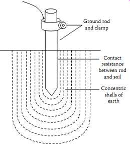
FIG. 8 illustrates a grounding rod (electrode). The resistance of the
grounding is made up of the following components:
1. Resistance of the electrode itself and that of the connection to it
2. Contact resistance of the surrounding earth to the electrode
3. Resistance of the earth immediately surrounding the grounding electrode or resistivity of earth, which is often the most significant factor
The grounding electrodes are usually made of a very conductive metal (copper or copper clad) with adequate cross sections so that the overall resistance is negligible. The resistance between the electrode and the surrounding earth is negligible if the electrode is free of paint, grease, or other coating, and if the earth is firmly packed.
The only component remaining is the resistance of the surrounding earth.
The electrode can be thought of as being surrounded by concentric shells of earth or soil, all of the same thickness. The closer the shell to the electrode, the smaller its surface; hence, the greater its resistance. The farther away the shells are from the electrode, the greater the surface of the shell; hence, the lower the resistance. Eventually, adding shells at a distance from the grounding electrode will no longer noticeably affect the overall earth resistance surrounding the electrode. The distance at which this effect occurs is referred to as the effective resistance area and is directly dependent on the depth of the grounding electrode.
When ground fault current flows from a ground rod to earth, it flows in all directions through a series of concentric spheres or shells, commonly referred to as effective cylinders of earth, surrounding the rod. The resistance of the closest sphere to the ground rod is the highest because it’s the smallest sphere.
As the distance from the ground rod is increased, the resistance becomes less because the sphere becomes larger. Eventually, a distance from the electrode is reached where the sphere resistance becomes zero. Therefore, in any ground resistance measurement only the part of earth resistance is considered that contributes a major part of the resistance. Theoretically, the earth resistance of the ground system should be measured up to infinite distance from the ground rod. However for practical purposes, the effective cylinder of earth (shells) that contributes the major portion of the earth resistance is two times the length of the ground rod.
In theory, the ground resistance may be derived from the general formula:
…where…
R is the ground resistance
r is the resistivity of the soil
L is the length of grounding electrode
A is the area
This formula illustrates why the shells of concentric earth decrease in resistance the farther they are from the ground rod: thickness of shell; Resistivity of soil; area; R
In the case of ground resistance, uniform earth (or soil) resistivity through out the volume is assumed, although this is seldom the case in nature. The equations for systems of electrodes are very complex and often expressed only as approximations. The most commonly used formula for single-ground electrode systems, developed by Professor H. R. Dwight of the Massachusetts Institute of Technology, is the following:
R is the resistance of the ground rod to the earth (or soil) (Ohm) L is the grounding electrode length r is the grounding electrode radius r is the average resistivity(Ohm-cm) of soil
__4.2 Effect of Ground Electrode Size and Depth on Resistance
Size: Increasing the diameter of the rod does not materially reduce its resistance. Doubling the diameter of the ground rod reduces resistance by less than 10%, as indicated in FIG. 9.
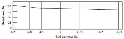
FIG. 9 Ground resistance versus ground size.
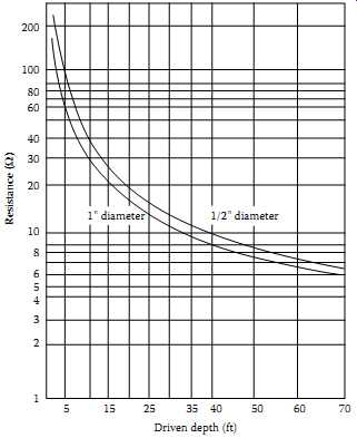
FIG. 10 Ground resistance versus ground rod depth.
=======
TBL. 2 Resistivity of Different Soils
Resistivity (O-cm) Soil Minimum Average Maximum Ashes, cinders, brine, waste 590 2,370 7,000 Clay, shale, gumbo, loam 340 4,060 16,300 Same, with varying proportions of sand and gravel 1,020 15,800 135,000 Gravel, sand, stones with little clay or loam 59,000 94,000 458,000
========
Depth: As a ground rod is driven deeper into the earth, its resistance is substantially reduced. In general, doubling the rod length reduces the resistance by an additional 40%, as seen in FIG. 10. The NEC requires a minimum of 8 ft (2.4 m) to be in contact with the soil. The most common is a 10 ft (3 m) cylindrical rod which meets the NEC code. A minimum diameter of 5/8 in. (1.59 cm) is required for steel rods and 1/2 in. (1.27 cm) for copper or copper clad steel rods. Minimum practical diameter for driving limitations for 10 ft (3 m) rods are 1/2 in. (1.27 cm) in average soil 5/8 in. (1.59 cm) in moist soil 3/4 in. (1.91 cm) in hard soil or more than 10 ft driving depths
__4.3 Effect of Soil Resistivity on Ground Electrode Resistance
Dwight's formula, cited previously, shows that the resistance of grounding electrodes to earth depends not only on the depth and surface area of grounding electrodes, but on soil resistivity as well. Soil resistivity is the key factor that determines what the resistance of a grounding electrode will be, and to what depth it must be driven to obtain low ground resistance. The resistivity of the soil varies widely throughout the world and changes seasonally. Soil resistivity is determined largely by its content of electrolytes, consisting of moisture, minerals, and dissolved salts. A dry soil has high resistivity if it contains no soluble salts, as shown in TBL. 2.
__4.4 Factors Affecting Soil Resistivity
Two samples of soil, when thoroughly dried, may become in fact very good insulators, having a resistivity in excess of 109 Ohm-cm. The resistivity of the soil sample is seen to change quite rapidly until approximately 20% or greater moisture content is reached as indicated in TBL. 3.
The resistivity of the soil is also influenced by temperature. TBL. 4 shows the variation of resistivity of sandy loam, containing 15.2% moisture, with temperature changes from 20°C to -15°C. In this temperature range, the resistivity is seen to vary from 7,200 to 330,000 Ohm-cm.
=====
TBL. 3 Effects of Moisture on Soil Resistivity Moisture Content (% by weight) Resistivity (Ohm-cm) Top Soil Sandy Loam
=====
TBL. 4 Effects of Temperature on Soil Resistivity Temperature Resistivity (Ohm-cm)
=====
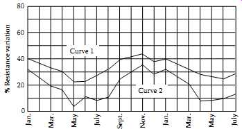
FIG. 11 Seasonal variation of earth resistance with an electrode of 3/4
in. pipe in stony clay soil. Depth of electrode in earth is 3 ft for curve
1, and 10 ft for curve 2.
======
TBL. 5 Effect of Salta Content on the Resistivity of Soil Added Salt (% by weight of moisture) Resistivity (Ohm-cm)
=======
TBL. 6 Effect of Temperature on the Resistivity of Soil Containing Salta Temperature (°C) Resistivity (Ohm-cm)
======
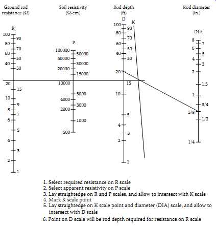
FIG. 12 A nomograph showing ground electrode depth versus ground electrode
resistance.
1. Select required resistance on R scale
2. Select apparent resistivity on P scale
3. Lay straightedge on R and P scales, and allow to intersect with K scale
4. Mark K scale point
5. Lay straightedge on K scale point and diameter (DIA) scale, and allow to intersect with D scale
6. Point on D scale will be rod depth required for resistance on R scale
======
Because soil resistivity directly relates to moisture content and temperature, it’s reasonable to assume that the resistance of any grounding system will vary throughout the different seasons of the year. Such variations are shown in FIG. 11. Since both temperature and moisture content become more stable at greater distances below the surface of the earth, it follows that a grounding system to be most effective at all times should be constructed with the ground rod driven down a considerable distance below the surface of the earth. Best results are obtained if the ground rod reaches the water table.
In some locations, the resistivity of the earth is so high that low-resistance grounding can be obtained only at considerable expense and with an elaborate grounding system. In such situations, it may be economical to use a ground rod system of limited size and to reduce the ground resistivity by periodically increasing the soluble chemical content of the soil. TBL. 5 shows the substantial reduction in resistivity of sandy loam brought about by an increase in chemical salt content.
Chemically treated soil is also subject to considerable variation of resistivity with changes in temperature, as shown in TBL. 6. If salt treatment is employed, it is, of course, necessary to use ground rods that will resist corrosion.
===
TBL. 7 Typical Grounding Resistance Values of Substations for Various Installations Installation Type Maximum Substation Grounding Resistance Values
a Commercial Metallic buildings =25 Ohm (per NEC) Wet wells, etc.
Homes Industrial General facilities 5 Ohm Chemical 3 Ohm Computer
<1-3 Ohm High-speed loading facilities for chemical
<1 Ohm Utilities Generating stations 1 Ohm a Large substations 1 Ohm District substations 1.5-5 Ohm Small substations 5 Ohm a For solidly grounded systems.
===
__4.5 Effect of Ground Electrode Depth on Resistance
In determining the approximate ground rod depth required to obtain a desired resistance, a grounding nomograph may be used. The nomograph, shown in FIG. 12, indicates that to obtain a grounding resistance of 20 Ohm in a soil with a resistivity of 10,000 Ohm-cm, a 5/8 in. OD rod must be driven 20 ft. Note that the values indicated on the nomograph are based on the assumption that the soil is homogenous and, therefore, has uniform resistivity. The nomograph value is an approximation.
__5. Ground Resistance Values
The NEC code states that the resistance to ground shall not exceed 25 Ohm. This is the maximum value of ground resistance and in most applications a much lower ground resistance is required.
"How low a ground resistance should be?" An arbitrary answer to this question is difficult. The lower the ground resistance, the safer, and for positive protection of personnel and equipment, it’s worth the effort to aim for less than 1 Ohm. It’s generally impractical to reach such a low resistance along a distribution system or a transmission line or in small substations.
In some regions, resistances of 5 Ohm or less may be obtained without much trouble. In others, it may be difficult to bring resistance of driven grounds below 100 Ohm.
Accepted industry standards stipulate that transmission substations should be designed not to exceed 1 Ohm resistance. In distribution substations, the maximum recommended resistance is for 5 Ohm or even 1 Ohm. In most cases, the buried grid system of any substation will provide the desired resistance.
In light industrial or in telecommunication central offices, 5 Ohm is often the accepted value. For lighting protection, the arrestors should be coupled with a maximum ground resistance of 1 Ohm. TBL. 7 shows typical values of ground resistance for various types of installations.
Grounding nomograph:
These parameters can usually be met with the proper application of basic grounding theory. There will always exist circumstances which will make it difficult to obtain the ground resistance required by the NEC or other safety standards. When these situations develop, several methods of lowering the ground resistance can be employed. These include parallel rod systems, deep-driven rod systems utilizing sectional rods and chemical treatment of the soil. Additional methods, discussed in other published data, are buried plates, buried conductors (counterpoise), electrically connected building steel, and electrically connected concrete reinforced steel.
Electrically connecting to existing water and gas distribution systems was often considered to yield low ground resistance; however, recent design changes utilizing nonmetallic pipes and insulating joints have made this method of obtaining a low-resistance ground questionable and in many instances unacceptable.
__6. Ground Resistance Measurements
To maintain sufficiently low resistance values of grounding systems, their periodic testing is required. The testing involves measurement to ensure that they don’t exceed design limits. The methods of measuring and testing the ground resistance and soil resistivity are as follows:
Two-point method • Three-point method • Fall-of-potential method • Ratio method • Four-point method • Touch potential measurements • Clamp-on method
The measurement of ground resistances may only be accomplished with specially designed test equipment. The most common method for measuring ground resistance uses the fall-of-potential principle of alternating current (AC) of 60 Hz or some higher frequency circulating between an auxiliary electrode and the ground electrode under test; the reading will be given in ohms and represents the resistance of the ground electrode to the surrounding earth. Also, one manufacturer has recently introduced a clamp-on ground resistance tester.
__6.1 Two-Point Method
This method may be used to measure the resistance of a single driven ground rod. It uses an auxiliary ground rod whose resistance is either known or can be measured. The resistance value of the auxiliary ground rod also must be very small compared to the resistance of the driven ground rod so that the measured value can be assumed to be wholly contributed by the driven ground rod. For example, this test might be applicable in the measurement of resistance of the single driven ground rod for a residence or in congested areas where finding room to drive two auxiliary rods may be a problem.
In this case, the municipal metallic water supply line can be assumed as the auxiliary ground rod whose resistance value is approximately 1 Ohm or less.
This value is quite small compared to the value of a single driven ground rod, whose value is in the order of 25 O. The reading obtained is that of the two grounds in series. The lead resistances will also be measured and should be deducted from the final measurements. This method is usually adequate where a go, no-go type of test is required. The connections for this test are shown in FIG. 13.
===
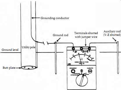
FIG. 13 Two-point ground resistance measurement method.
Ground level Utility pole Grounding conductor Ground rod Terminals shorted with jumper wire Auxiliary rod (Y-Z shorted) Butt plate
===
__6.2 Three-Point Method
This method is similar to the two-point method except it uses two auxiliary rods. To obtain accurate values of resistance measurements, the resistance of the auxiliary electrodes should be approximately equal to or less than that of the electrode under test. The connections for the three-point method are shown in FIG. 14.
FIG. 14 Three-point test method and its equivalent circuit.
Either AC of 60 Hz or DC may be used for making this test. The advantage of using AC is that it minimizes the effects of stray currents on measurement readings. However, if stray currents happen to be of the same frequency, error will be introduced in the readings. The use of DC for making this test will totally eliminate the AC stray currents. However, stray DC and formation of gas around the electrodes will introduce error in the readings when using DC for this test. The effect of stray DCs can be minimized by taking readings with current in the opposite direction. The average of the two readings will give an accurate test value. Apply currents only long enough to take readings.
The resistance value of the test electrode can be calculated as follows. Let ....
__6.3 Fall-of-Potential Method
This method measures grounding electrode resistance based upon the principle of potential drop across the resistance. It also uses two auxiliary electrodes (one current rod and the other a potential rod) that are placed at a sufficient distance from the test electrodes; a current of known magnitude is passed through the electrode under test and one of the auxiliary electrodes (current rod). The drop in potential between the electrode under the test and the second auxiliary electrode (potential rod) is measured. The ratio of volt age drop (V) to the known current (I) will indicate the resistance of the grounding circuit. Either a DC or AC voltage source may be used for con ducting this test.
Several problems and errors may be encountered with this method, such as (i) stray currents in earth may cause voltmeter readings to be either high or low and (ii) the resistance of auxiliary electrode and electrical leads may introduce errors in the voltmeter reading. This error can be minimized by using a voltmeter of high impedance value.
This method can be used with either a separate voltmeter and ammeter or a single instrument which provides a reading directly in ohms (see FIG. 15). To measure the resistance of a grounding electrode, the current electrode is placed at a suitable distance from the grounding
electrode under test. As shown in FIG. 16, the potential difference between rods X and Y is measured by a voltmeter, and the current flow between rods X and Z is measured by an ammeter. (Note: X, Y, and Z may be referred to as X, P, and C in a three-point tester or C1, P2, and C2 in a four-point tester.) By Ohm's law E = RI or R = E/I. By this formula, we may obtain the ground electrode resistance R. If E = 20 V and I = 1 A, then ...
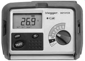
FIG. 15 Fall-of-potential method ground resistance instrument.
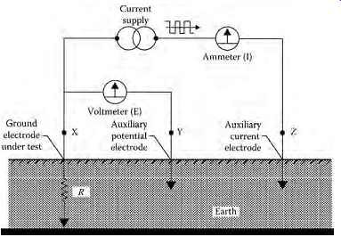
FIG. 16 Fall-of-potential method.
__6.3.1 Position of the Auxiliary Electrodes on Measurements
The goal in precisely measuring the resistance to ground is to place the auxiliary current electrode Z far enough from the ground electrode under test so that the auxiliary potential electrode Y will be outside of the effective resistance areas (effective cylinder of earth) of both the ground electrode and the auxiliary current electrode. The best way to find out if the auxiliary potential rod Y is outside the effective resistance areas is to move it between X and Z and to take a reading at each location. If the auxiliary potential rod Y is in an effective resistance area (or in both if they overlap as in FIG. 17a), by displacing it the readings taken will vary noticeably in value. Under these conditions, no exact value for the resistance to ground may be determined.
On the other hand, if the auxiliary potential rod Y is located outside of the effective resistance areas, as in FIG. 17b, as Y is moved back and forth the reading variation is minimal. The readings taken should be relatively close to each other, and are the best values for the resistance to ground of the ground X. The readings should be plot ted to ensure that they lie in a " plateau" region as shown in FIG. 17b. The region is often referred to as the 62% area which is discussed in the following section.
====
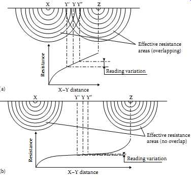
FIG. 17 Effective resistance areas (cylinders of earth) (a) overlapping
and (b) not overlapping. (a) (b) X-Y distance Effective resistance areas
(no overlap) Reading variation Resistance Y_ Y XZ Y_ X-Y distance Effective
resistance areas (overlapping) Reading variation Resistance
====
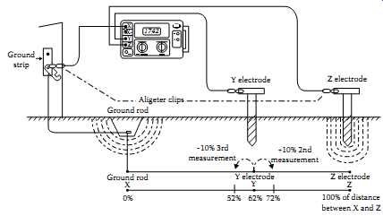
FIG. 18 Fall-of-potential method showing potential rod location at 62%
distance from the electrode under test.
====
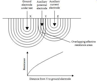
FIG. 19 Overlapping effective resistance areas.
Ground electrode under test Auxiliary potential electrode XYZ Auxiliary current electrode Overlapping effective resistance areas Distance from Y to ground electrode Resistance
====
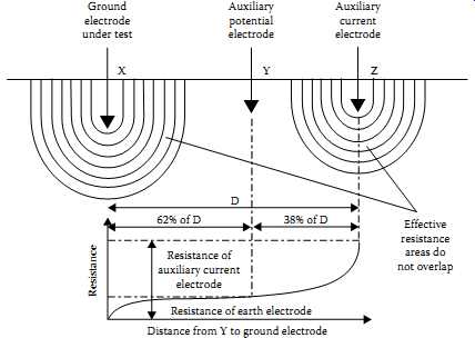
FIG. 20 Effective resistance areas not overlapping.
Distance from Y to ground electrode Resistance of earth electrode 62% of D 38% of D D Resistance of auxiliary current electrode Effective resistance areas don’t overlap Auxiliary current electrode Auxiliary potential electrode Ground electrode under test XYZ Resistance
===
__6.3.2 Measuring Resistance of Ground Electrodes (62% Method)
The 62% method is an extension of the fall-of-potential method and has been adopted after graphical consideration and after actual test. It’s the most accurate method but is limited by the fact that the ground tested is a single unit.
This method applies only when all three electrodes are in a straight line and the ground is a single electrode, pipe, or plate, etc., as is shown in FIG. 18.
Consider FIG. 19, which shows the effective resistance areas (concentric shells) of the ground electrode X and of the auxiliary current electrode Z. The effective cylinders of earth of the X and Z rods overlap. If readings were taken by moving the auxiliary potential electrode Y toward either X or Z, the reading differentials would be great and one could not obtain a reading within a reasonable band of tolerance. The sensitive areas overlap and act constantly to increase resistance as Y is moved away from X.
Now consider FIG. 20, where the X and Z electrodes are sufficiently spaced so that the areas of effective resistance don’t overlap. If we plot the resistance measured, we find that the measurements level off when Y is placed at 62% of the distance from X to Z, and that the readings on either side of the initial Y setting are most likely to be within the established tolerance band. This tolerance band is defined by the user and expressed as a percent of the initial reading: ±2%, ±5%, ±10%, etc.
===
TBL. 8 Approximate Distance (ft) to Auxiliary
Electrodes Using the 62% Method Depth Driven Distance to Y Distance to Z 64572 85080 10 55 88 12 60 96 18 71 115 20 74 120 30 86 140
===
TBL. 9 Multiple Electrode System Distance (ft) Maximum Grid Distance; Distance to Y Distance to Z
===
__6.3.3 Auxiliary Electrode Spacing
No definite distance between X and Z can be given, since this distance is relative to the diameter of the electrode tested, its length, the homogeneity of the soil tested, and particularly, the effective resistance areas. However, an approximate distance may be determined from TBL. 8, which is given for a homogeneous soil and an electrode of 1 in. in diameter. (For a diameter of 1/2 in., reduce the distance by 10%; for a diameter of 2 in. increase the distance by 10%.) It’s recommended that the test should be made for ground electrode resistance for each season of the year. The data should be retained for each season for comparison and analysis. Serious deviation of the test data from previous years, other than seasonal variations, could mean electrode corrosion.
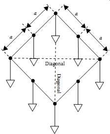
FIG. 21 Multiple electrode system (ground grid).
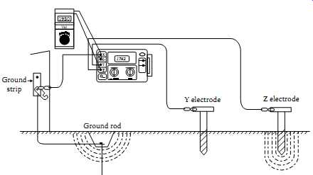
FIG. 22 Testing for stray voltages.
__6.3.4 Multiple Electrode System
A single driven ground electrode is an economical and simple means of making a good ground system. But sometimes a single rod won’t provide sufficient low resistance, and several ground electrodes will be driven and connected in parallel by a cable. Very often when two, three, or four ground electrodes are used, they are driven in a straight line; when four or more are used, a hollow square configuration is used and the ground electrodes are still connected in parallel and equally spaced as shown in FIG. 21.
In multiple electrode systems, the 62% method electrode spacing may no longer be applied directly (see TBL. 9). The distance of the auxiliary electrodes is now based on the maximum grid distance (i.e., in a square, the diagonal; in a line, the total length, e.g., a square having a side of 20 ft will have a diagonal of approximately 28 ft).
Excessive noise. Excessive noise may interfere with testing because of the long leads used to perform a fall-of-potential test. A voltmeter can be utilized to identify this problem. Connect the X, Y, and Z cables to the auxiliary electrodes as for a standard ground resistance test. Use the voltmeter to test the voltage across terminals X and Z as shown in FIG. 22. The voltage reading should be within the stray voltage tolerances acceptable to the ground tester being used. If the test exceeds this value, try the following techniques:
1. Braid the auxiliary cables together. This often has the effect of canceling out the common mode voltages between these two conductors.
2. If the previous method fails, try changing the alignment of the auxiliary cables so that they are not parallel to power lines above or below the ground.
3. If a satisfactory low voltage value is still not obtained, the use of shielded cables may be required. The shield acts to protect the inner conductor by capturing the voltage and draining it to ground, as shown in FIG. 23.
Excessive auxiliary rod resistance. The inherent function of a fall-of-potential ground tester is to input a constant current into the earth and measure the voltage drop by means of auxiliary electrodes. Excessive resistance of one or both auxiliary electrodes can inhibit this function. This is caused by high soil resistivity or poor contact between the auxiliary electrode and the surrounding dirt. To ensure good contact with the earth, stamp down the soil directly around the auxiliary electrode to remove air gaps formed when inserting the rod. If soil resistivity is the problem, pour water around the auxiliary electrodes. This reduces the auxiliary electrode's contact resistance without affecting the measurement.
=====
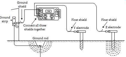
FIG. 23 Use of shielded cables to minimize stray voltages.
X 1742 X Y Z Y electrode Float shield Float shield Connect all three shields together Z electrode Ground rod Ground shield Ground strip
=====
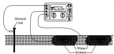
FIG. 24 Use of screens as auxiliary electrodes. Ground rod
====
Tar or concrete mat. Sometimes a test must be performed on a ground rod that is surrounded by a tar or concrete mat, where auxiliary electrodes cannot be driven easily. In such cases, metal screens and water can be used to replace auxiliary electrodes, as shown in FIG. 24. Place the screens on the floor the same distance from the ground rod under test as you would auxiliary electrodes in a standard fall-of-potential test. Pour water on the screens and allow it to soak in. These screens will now perform the same function as would driven auxiliary electrodes.
__6.4 Ratio Method
This method uses a Wheatstone bridge or an ohmmeter to measure the series resistance of grounding electrode and the auxiliary electrode. The test connections are shown in FIG. 25. A slide wire potentiometer is used with a Wheatstone bridge for this test. The potentiometer is connected across the grounding electrode under test and the first auxiliary electrode. The sliding contact of the potentiometer is connected to the second auxiliary electrode through a detector for determining the null point. The resistance of the test electrode and first auxiliary electrode is measured first by the Wheatstone bridge or ohmmeter. Then, using the potentiometer and Wheatstone bridge, a new null point is determined with the second electrode in the test circuit.
The resistance of the grounding electrode is the ratio of the test electrode resistance to the total resistance of the two in series. The procedure and equations are as follows:
Measure Rx + Ry by means of a Wheatstone bridge or ohmmeter Determine from the potentiometer the ratio of RA/(RA + RB) Insert second auxiliary electrode ( Rz) in test circuit and obtain null point
__6.5 Soil Resistivity Measurements (Four-Point Measurement)
The purpose of soil resistivity measurements is threefold. First, such data are used to make subsurface geophysical surveys as an aid in identifying ore locations, depth to bedrock, and other geological phenomena. Second, resistivity has a direct impact on the degree of corrosion in underground pipe lines. A decrease in resistivity relates to an increase in corrosion activity and therefore dictates the protective treatment to be used. Third, soil resistivity directly affects the design of a grounding system, and it’s to that task that this discussion is directed. When designing an extensive grounding system, it’s advisable to locate the area of lowest soil resistivity in order to achieve the most economical grounding installation.
The two types of resistivity measurements are two-point method and four point method. The two-point method is simply the resistance measured between two points. For most applications, the most accurate method is the four-point method. The four-point method, as the name implies, requires the insertion of four equally spaced, and in-line, electrodes into the test area.
A known current from a constant current generator is passed between the outermost electrodes. The potential drop (as a function of the resistance) is then measured across the two innermost electrodes. The ground resistivity is based on the formula given below and the meter is calibrated to read directly in ohms.
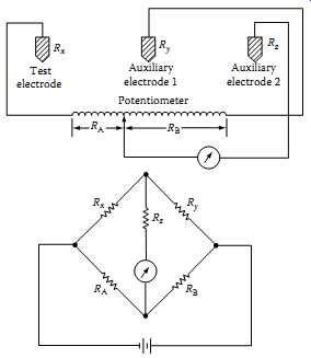
FIG. 25 Ratio method of measuring ground resistance.
This value is the average resistivity of the ground at a depth equivalent to the distance A between two electrodes.
...where A is the distance between the electrodes (cm) B is the electrode depth (cm) R is the ohmic value as measured by four-terminal ground tester If A > 20B, the formula becomes:
() p= 2 with in cm AR A r
() = 191.5 with in ft AR A r
=Ohm soil resistivity ( -cm) r
__6.6 Touch Potential Measurements
The primary reason for performing ground resistance measurements is to ensure electrical safety of personnel and equipment. Periodic ground electrode or grid resistance measurements are recommended when:
1. The electrode/grid is relatively small and can be conveniently disconnected
2. Corrosion induced by low soil resistivity or galvanic action is suspected
3. Ground faults are very unlikely to occur near the ground under test
In certain cases, the degree of electrical safety can be evaluated from a different perspective. Voltage gradient are a safety concern in large high voltage switchyards and substations. Therefore, the ground grid system of these facilities is designed to ensure that the voltage gradients due to induced or fault currents remain at low value and not pose a danger to personnel or equipment. The maximum limit of voltage for these gradients is defined in terms of the following:
Touch potential : Touch potential is the voltage difference between a person's arm and the feet, caused by the voltage gradient due to fault or induced current. It’s assumed that the current passes through the heart and therefore this potential should be kept to near zero to safeguard personnel who might accidentally come in contact with equipment and structures in a switchyard or substations.
Step potential: Step potential is the voltage difference between a person's feet, caused by the voltage gradient due to fault or induced current.
It’s assumed that the current passes through the legs and therefore this potential should be kept to near zero to safeguard personnel.
Touch potential measurements are recommended when the following factors are present.
1. It’s physically or economically impossible to disconnect the ground to be tested.
2. Ground faults could reasonably be expected to occur near the ground to be tested, or near equipment grounded by the ground to be tested.
3. The footprint of grounded equipment is comparable to the size of the ground to be tested. (The footprint is the outline of the part of equipment in contact with the earth.) When performing touch potential measurements, a four-pole ground resistance tester is used. During the test, the instrument induces a low-level fault into the earth at some proximity to the subject ground. The instrument displays touch potential in volts per ampere of fault current. The displayed value is then multiplied by the largest anticipated ground fault current to obtain the worst case touch potential for a given installation.
For example, if the instrument displayed a value of 0.100 when connected to a system where the maximum fault current was expected to be 5000A, the maximum touch potential would be 500 V.
Touch potential measurements are similar to fall-of-potential measurements in that both measurements require placement of auxiliary electrodes into or on the earth. Spacing the auxiliary electrodes during touch potential measurements differs from fall-of-potential electrode spacing, as shown in FIG. 26.
===
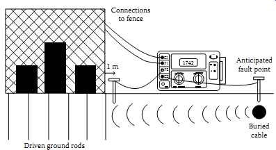
FIG. 26 Touch potential measurements. C1 P1 1742 Connections to fence,
Anticipated fault point, Buried cable 1 m; Driven ground rods P2 C2
===
Consider the following scenario: If the buried cable depicted in FIG. 26 experienced an insulation breakdown near the substation shown, fault currents would travel through the earth toward the substation ground, creating a voltage gradient. This voltage gradient may be hazardous or potentially lethal to personnel who came in contact with the affected ground.
To test for approximate touch potential values in this situation, proceed as follows. Connect cables between the fence of the substation and C1 and P1 of the four-pole earth resistance tester. Position an electrode in the earth at the point at which the ground fault is anticipated to occur, and connect it to C2.
In a straight line between the substation fence and the anticipated fault point, position an auxiliary electrode into the earth 1 m (or one arm's length) away from the substation fence, and connect it to P2. Turn the instrument on, select the 10 mA current range, and observe the measurement. Multiply the displayed reading by the maximum fault current of the anticipated fault.
By positioning the P2 electrode at various positions around the fence adjacent to the anticipated fault line, a voltage gradient map may be obtained.
__6.7 Clamp-On Ground Resistance Measurement
This measurement method is new and quite unique. It offers the ability to measure the resistance without disconnecting the ground. This type of measurement also offers the advantage of including the bonding to ground and the overall grounding connection resistances.
__6.7.1 Principle of Operation
Usually, a common distribution line grounded system can be simulated as a simple basic circuit as shown in FIG. 27, or an equivalent circuit as shown in FIG. 28. If voltage E is applied to any measured grounding pole Rx through a special transformer, current I flows through the circuit, thereby establishing the following equation:
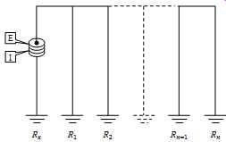
FIG. 27 Simple basic circuit of distribution grounded system.
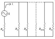
FIG. 28 Equivalent circuit of simple distribution grounded system.
Therefore, E/I = Rx is established. If I is detected with E kept constant, measured grounding pole resistance can be obtained.
Refer again to FIGs 27 and 11.28. Current is fed to a special transformer via a power amplifier from a 1.6 kHz constant-voltage oscillator. This current is detected by a detection current transformer (CT). Only the 1.6 kHz signal frequency is amplified by a filter amplifier before being fed into analog/ digital (A/D)-converter, and after synchronous rectification it’s displayed on the liquid crystal display (LCD).
The filter amplifier is used to cut off earth current at commercial frequency and high-frequency noise. Voltage is detected by coils wound around the injection CT and then amplified and rectified to be compared by a level comparator. If the clamp is not closed properly, an open jaws annunciator appears on the LCD. The clamp-on ground resistance measurement instrument is shown in FIG. 29.
__6.7.2 In-Field Measurement
The following are examples of ground resistance measurements in typical field situations:
Pole-mounted transformer: Remove any molding covering the ground conductor, and provide sufficient room for the jaws of the clamp-on ground tester. The jaws must be able to close easily around the conductor. The jaws can be placed around the ground rod itself.
Note: The clamp must be placed so that the jaws are in electrical path from the system neutral or ground wire to the ground rod or rods as the circuit provides.
Select the current range A. Clamp onto the ground conductor and measure the ground current. The maximum range is 30 A. If the ground current exceeds 30 A, ground resistance measurements are not possible. "Don’t proceed further with the measurement." Having noted the ground current, select the ground resistance range Ohm and measure the resistance directly.
The reading you measure with the ground tester indicates not just the resistance of the rod, but of the connection to the system neutral and all bonding connections between the neutral and the rod.
Note that in FIG. 30, there exist both a butt plate and a ground rod.
In this type of circuit, it’s necessary to place the tester jaws above the bond so that both grounds are included in the test. For future reference, note the date, ohms reading, current reading, and pole number. Replace any molding you may have removed from the conductor.
Note: A high reading indicates one or more of the following:
Poor ground rod.
Open ground conductor.
High resistance bonds on the rod or splices on the conductor; watch for buried split butts, clamps, and hammer-on connections.
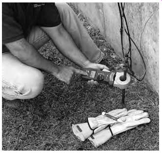
FIG. 29 Clamp-on ground resistance measurement instrument.
Service entrance or meter: Follow basically the same procedure as in the first example. Notice that FIG. 31 shows the possibility of multiple ground rods and in FIG. 32, the ground rods have been replaced with a water pipe ground. You may also have both types acting as a ground. In these cases, it’s necessary to make the measurements between the service neutral and both grounded points.
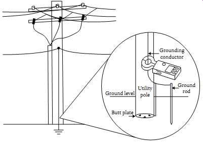
FIG. 30 Ground resistance measurement of pole-mounted transformer. Utility
pole Ground level Ground rod Grounding conductor
Butt plate
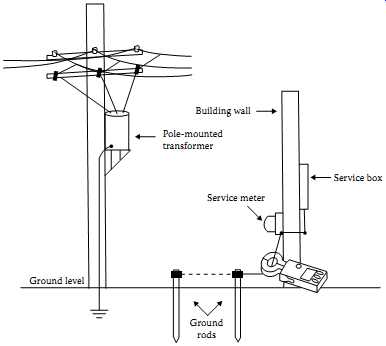
FIG. 31 Ground resistance measurement of service entrance having multiple
ground rods.
Ground level Ground rods Service meter Building wall Pole-mounted transformer
Service box
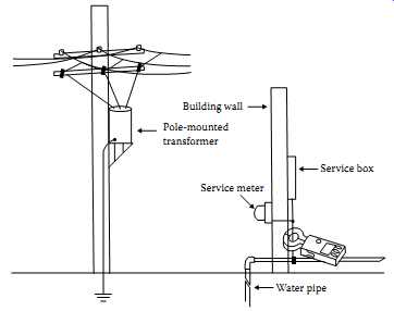
FIG. 32 Ground resistance measurement of service entrance with water
pipe ground. Service meter, Water pipe, Building wall, Pole-mounted transformer;
Service box; Pad-mounted transformer
Note: Never open transformer enclosures. They are the property of the electrical utility. If the ground test needs to be performed with the utility transformer, coordinate with the utility personnel for such a test.
"Observe all safety requirements-dangerously high voltage is present." Locate and number all rods (usually only a single rod is present). If the ground rods are inside the enclosure, refer to FIG. 33 and if they are outside the enclosure, refer to FIG. 34. If a single rod is found within the enclosure, the measurement should be taken on the conductor just before the bond on the ground rod. Often, more than one ground conductor is tied to this clamp, looping back to the enclosure or neutral.
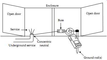
FIG. 33 Ground resistance measurement of pad-mounted transformer with
ground rods inside the enclosure. Open door Enclosure Buss Concentric neutral
Ground rod(s) Open door Service
Underground service:
In many cases, the best reading can be obtained by clamping the instrument onto the ground rod itself, below the point when the ground conductors are attached to the rod, so that you are measuring the ground circuit. Care must be taken to find a conductor with only one return path to the neutral.
Generally, a very low reading at the measurement indicates that you are on a loop and you need to test closer to the rod. In FIG. 34, the ground rod is located outside the enclosure. Clamp at the indicated measuring point to obtain the correct reading. If more than one rod exists at different comers of the enclosure, it will be necessary to determine how they are connected to properly measure the ground resistance.
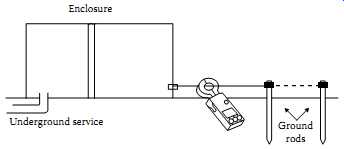
FIG. 34 Ground resistance measurement of pad-mounted transformer with
ground rods outside the enclosure. Ground rods; Enclosure; Underground
service
__6.7.3 Transmission Towers
"Observe all safety requirements-dangerously high voltage is present." Locate the ground conductor at the base of the tower.
Note: Many different configurations exist. Care should be taken when searching for the ground conductor. FIG. 35 shows a single leg mounted on a concrete pad with an external ground conductor. The point at which you clamp the ground tester should be above all splices and connections which allow for multiple rods, butt wraps, or butt plates.
__6.7.4 Central Office Locations
The main ground conductor from ground window or ground plane is often too large to clamp around. Due to the wiring practices within the central office, there are many locations at which you can look at the water pipe or counterpoise from within the building. An effective location is usually at the ground buss in the power room, or near the backup generator.
By measuring at several points and comparing the readings, you will be able to identify neutral loops, utility grounds, and central office grounds. The test is effective and accurate because the ground window is connected to the utility ground at only one point, according to standard practices.
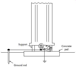
FIG. 35 Ground resistance measurement of transmission tower with a single
leg mounted on a concrete pad with an external ground conductor. Concrete
pad Ground rod, Support
__7. Ground Grid Integrity Measurements
Neither the ground resistance measurements or the touch potential measurements provide information on the ability of grounding conductors and connections to carry ground fault currents safely to earth. Experience has shown that the ground fault current can cause a lot of damage to equipment and pose safety hazard to personnel when it does not find a low- impedance path to the ground grid and thus to mother earth. Therefore, it makes sense to periodically check and verify the integrity of the ground grid connections.
The objective of this measurement is to determine whether the equipment, frame, structures, or enclosure grounds are connected to the grounding electrode or ground grid with low resistance. The resistance value of such connections is expected to be very low (100 µOhm or less). The best way for making tests for integrity of ground grid connections is to use a large but practical current and some means of detecting the voltage drop caused by this current. A test set is available to conduct this measurement using AC current. This test method is known as the high-current test method. This method consists of passing 300 A through the ground grid between a reference ground (usually a transformer neutral) and the ground (conductor and connections) to be tested. The voltage drop and the current magnitude and direction are monitored to verify the integrity of the ground connections.
The GTS-300 test set is shown in FIG. 36. The test connections for conducting this test are shown in FIG. 37.
The below listed guidelines are offered when using the high-current method of testing the continuity of ground grids and grounds. However, it should be kept in mind that these are only guidelines since each ground has to be considered on its own merits relative to other grounds in the immediate vicinity.
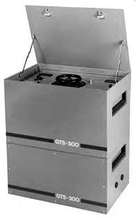
FIG. 36 Ground grid integrity test set, GTS-300.
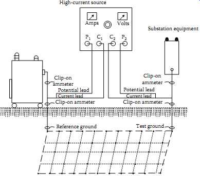
FIG. 37 High-current method of testing ground grid integrity.[Amps High-current
source Volts P1 Clip-on ammeter Clip-on ammeter Substation equipment Clip-on
ammeter Clip-on ammeter Reference ground Test ground Potential lead Potential
lead Current lead Current lead P2 C2 C1]
1. The voltage drop of the ground grid rises approximately 1 V for each 50 ft of straight distance from the reference point.
2. On equipment with single ground the ground can be considered satisfactory if the voltage drop is in line with item 1 above and at least 200A flow to the ground conductor under test into the grid.
On most equipment of this type, 300A will flow to the grid; however, in some cases current will also flow through foundation bolts and or conduits.
3. On equipment with multi-grounds, a ground can be considered satisfactory if the voltage drop is in line with item 1 above and at least 150A flow to the ground conductor under test into the grid.
If the current to the grid is less than 150A, the ground should be disconnected from the equipment and 300 A again should be passed through the ground. If the ground passes the 300A and the voltage drop does not increase more than 0.5V over the previous level, the ground can be considered satisfactory.
"Caution: Before any ground is removed from an equipment be sure to parallel it with a 2/0 CU temporary ground, such as a truck ground or other grounds before it’s disconnected."
4. To test transformer neutral or reference point pass 300A through the transformer neutral at a point above grade but below any bonding connections or clamps on the tank. If at least 150 A flow to the ground grid, the reference point can be considered satisfactory.
5. Establish a reference ground, preferably a transformer neutral. From a high-current AC source (GTS-300) connect one test lead to ground being tested as shown in FIG. 37. Connect the test lead at a point above grade but below the bonding connections or clamps. Pass 300 A through the ground grid and record the voltage drop across the grid. Using a clip-on ammeter, measure the amount of test current flowing above (to the equipment) and below (to the grid) the test lead on the ground being tested. The voltage drop should be in accordance with item 1 above. The test amperes should be in accordance with items 2 and 3 in this list.