AMAZON multi-meters discounts AMAZON oscilloscope discounts
1. Introduction
The direct-current (dc) and synchronous motors we have discussed thus far have one thing in common: both are the doubly-fed type. These motors have direct current in their field windings and alternating current (ac) in their armature windings. Since the electrical power is delivered directly to the armature of a dc motor via a commutator, it can also be referred to as a conduction motor.
We now consider a motor in which the rotor receives its power not by conduction but by induction and is therefore called an induction motor. A winding that receives its power exclusively by induction constitutes a transformer. Therefore, an induction motor is a transformer with a rotating secondary winding. From the above discussion, the following must be evident:
An induction motor is a singly-fed motor. Therefore, it does not require a commutator, slip-rings, or brushes. In fact, there are no moving contacts between the stator and the rotor. This results in a motor that is rugged, reliable, and almost maintenance free.
The absence of brushes eliminates the electrical loss due to the brush voltage drop and the mechanical loss due to friction between the brushes and commutator or the slip-rings. Thus, an induction motor has a relatively high efficiency.
An induction motor carries alternating current in both the stator and the rotor windings.
An induction motor is a rotating transformer in which the secondary winding receives energy by induction while it rotates.
There are two basic types of induction motors: single-phase induction motors and polyphase induction motors. Single-phase induction motors are favored for domestic applications. A large number of these motors are built in the fractional-horsepower range. We will discuss single-phase induction motors in Section 10.
On the other hand, polyphase induction motors cover the entire spectrum of horsepower ratings and are preferably installed at locations where a polyphase power source is easily accessible.
Owing to the widespread generation and transmission of three-phase power, most polyphase induction motors are of the three-phase type. In this section, we confine our discussion exclusively to three-phase induction motors. The theoretical development, however, can be easily extended to an n-phase induction motor where n > = 2.
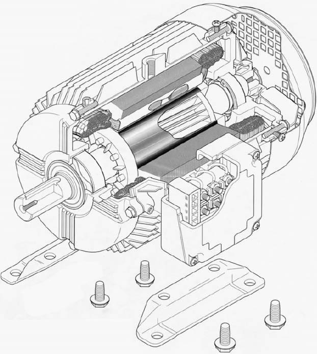
Figure: Sectional view of a three-phase, high efficiency, induction motor.
2. Construction
The essential components of an induction motor are a stator and a rotor.
Stator:
The outer (stationary) member of an induction motor is called the stator and is formed by stacking thin-slotted, highly permeable steel laminations inside a steel or cast-iron frame. The frame provides mechanical support to the motor. Although the frame is made of a magnetic material, it’s not designed to carry magnetic flux.
Identical coils are wound (or placed) into the slots and then connected to form a balanced three-phase winding. For further insight on the placement of the coils and their internal connections, refer to Section 7.
Rotor:
The rotor is also composed of thin-slotted, highly permeable steel laminations that are pressed together onto a shaft. There are two types of rotors: a squirrel-cage rotor and a wound rotor.
The squirrel-cage rotor is commonly used when the load requires little starting torque. For small motors, such a winding is molded by forcing a molten conducting material (quite often, aluminum) into the slots in a die-casting process.
Circular rings called the end-rings are also formed on both sides of the stack.
These end-rings short-circuit the bars on both ends of the rotor, as explained in Section 8, where we referred to the squirrel-cage winding as a damper winding.
For large motors, the squirrel-cage winding is formed by inserting heavy conducting bars (usually of copper, aluminum, or their alloys) into the slots and then welding or bolting them to the end-rings.
Each pair of poles has as many rotor phases as there are bars because each bar behaves independently of the other. It’s a common practice to skew the rotor laminations to reduce cogging and electrical noise in the motor. We will have more to say about it in a later section.
It becomes necessary to use a wound rotor when the load requires a high starting torque. A wound rotor must have as many poles and phases as the stator.
In fact, the placement of coils in a wound rotor is no different from that in the stator. The three-phase windings on the rotor are internally connected to form an internal neutral connection. The other three ends are connected to the slip-rings, as explained in Section 8. With the brushes riding on the slip-rings, we can add external resistances in the rotor circuit. In this way the total resistance in the rotor circuit can be controlled. By controlling the resistance in the rotor circuit we are, in fact, controlling the torque developed by the motor. We will show that the speed at which an induction motor develops the maximum torque (called the breakdown speed) depends upon the rotor resistance. As the rotor resistance increases, the breakdown speed decreases. Therefore, it’s possible to obtain maximum torque at starting (zero speed) by inserting just the right amount of resistance in the rotor circuit. However, a wound-rotor induction motor is more expensive and less efficient than a squirrel-cage induction motor of the same rating. For these reasons, a wound-rotor induction motor is used only when a squirrel-cage induction motor cannot deliver the high starting torque demanded by the load.
3. Principle of Operation
When the stator winding of a three-phase induction motor is connected to a three-phase power source, it produces a magnetic field that (a) is constant in magnitude and (b) revolves around the periphery of the rotor at the synchronous speed. The details of how the revolving field is produced and the torque is developed are given in Section 3. A brief review is presented here.
If f is the frequency of the current in the stator winding and P is the number of poles, the synchronous speed of the revolving field is:
.... in revolutions per minute (rpm), or ...
... in radians per second.
The revolving field induces electromotive force (emf) in the rotor winding.
Since the rotor winding forms a closed loop, the induced emf in each coil gives rise to an induced current in that coil. When a current-carrying coil is immersed in a magnetic field, it experiences a force (or torque) that tends to rotate it. The torque thus developed is called the starting torque. If the load torque is less than the starting torque, the rotor starts rotating. The force developed and thereby the rotation of the rotor are in the same direction as the revolving field. This is in accordance with Faraday's law of induction. Under no load, the rotor soon achieves a speed nearly equal to the synchronous speed. However, the rotor can never rotate at the synchronous speed because the rotor coils would appear stationary with respect to the revolving field and there would be no induced emf in them. In the absence of an induced emf in the rotor coils, there would be no current in the rotor conductors and consequently no force would be experienced by them.
In the absence of a force, the rotor would tend to slow down. As soon as the rotor slows down, the induction process takes over again. In summary, the rotor receives its power by induction only when there is a relative motion between the rotor speed and the revolving field. Since the rotor rotates at a speed lower than the synchronous speed of the revolving field, an induction motor is also called an asynchronous motor.
Let N, (or w,) be the rotor speed at a certain load. With respect to the motor, the revolving field is moving ahead at a relative speed of ...
The relative speed is also called the slip speed. This is the speed with which the rotor is slipping behind a point on a fictitious revolving pole in order to produce torque. However, it’s a common practice to express slip speed in terms of the slip (s), which is a ratio of the slip speed to the synchronous speed. That is, ...
Although the above equation yields the slip on a per-unit basis, it’s customary In terms of the synchronous speed and the per-unit slip, we can express the to express it as a percentage of synchronous speed (percent slip). rotor speed as ....
When the rotor is stationary, the per-unit slip is 1 and the rotor appears exactly like a short-circuited secondary winding of a transformer. The frequency of the induced emf in the rotor winding is the same as that of the revolving field. However, when the rotor rotates, it’s the relative speed of the rotor Nr (or mr) that is responsible for the induced emf in its windings. Thus, the frequency of the induced emf in the rotor is ....
The above equation highlights the fact that the rotor frequency depends upon the slip of the motor. At standstill, the slip is 1 and the rotor frequency is the same as ...that of the revolving field. However, the rotor frequency decreases with the decrease in the slip. As the slip approaches zero, so does the rotor frequency. An induction motor usually operates at low slip. Hence the frequency of the induced emf in the rotor is low. For this reason, the core loss in the rotor magnetic circuit is most often ignored.
EXAMPLE 1
A 208-V, 60-Hz, 4-pole, three-phase induction motor has a full-load speed of 1755 rpm. Calculate (a) its synchronous speed, (b) the slip, and (c) the rotor frequency.
SOLUTION
(a) The synchronous speed of the induction motor is ...
(b) At full load, the slip is ...
(c) The rotor frequency at full load is ....
Exercises:
The rotor speed of a 440-V, 50-Hz, 8-pole, three-phase induction motor is 720 rpm. Determine (a) the synchronous speed, (b) the slip, and (c) the rotor frequency.
If the rotor frequency of a 6-pole, 50-Hz, three-phase induction motor is 3 Hz, determine (a) the slip and (b) the rotor speed.
The magnetic field produced by a three-phase induction motor revolves at a speed of 900 rpm. If the frequency of the applied voltage is 60 Hz, determine the number of poles in the motor. When the rotor turns at a speed of 800 rpm, what is the percent slip of the motor?