Home
Articles
Forum (Message Board)
Glossary
Books
Sitemap
. In our discussion of the asynchronous generator (actually, an induction motor caused to run above its synchronous speed) a simple illustrative example was postulated of a train fed from an AC line and propelled by an induction motor. On a downhill grade, the motor could be caused to operate above its synchronous speed, thus becoming an asynchronous generator delivering power back into the AC line. This kind of operation can also manifest itself as regenerative braking—slowing down the train and relieving wear on the frictional brakes. Note that energy is returned to the AC power line rather than being dissipated in a resistance or in the motor itself as in dynamic braking.
However, such a simplified propulsion system with the induction motor powered directly from the AC line cannot provide much braking effort—most of the time, the motor would not be acting as an asynchronous generator and would be busy adding to, rather than subtracting from, the tractive effort of the train. In practice, therefore, a different arrangement is used—one that permits regenerative braking almost down to zero speed of the train. Such action greatly enhances safety, decreases maintenance of the frictional brakes, and increases the overall operating efficiency of the electrification system.
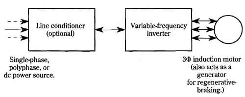
Such a system is shown in FIG. 27. Notice that the input of electrical power can be from either an AC or a DC line. If an AC line is involved, the line conditioner is a rectifier, if operation is from a DC line, the line conditioner would be a filter to protect railroad signaling apparatus from noise and transient contamination. The basic idea in either case is to have DC power available to operate a variable frequency inverter. Such an inverter is often designed around GTOs with ratings at kilovolt and kilo-ampere levels. By supplying the gates of the GTOs with appropriate control pulses, the induction motor can be operated from a variable-frequency, three-phase format. Additionally, the GTO gate logic makes use of pulse-width modulation to in crease the voltage applied to the motor as frequency is increased.
-- --

FIG. 27 Basic scheme for regenerative braking from induction-motor
drive. The frequency of the inverter is controlled by the vehicle operator.
When the frequency is low enough while the motor is still turning at
above- synchronous speed, the motor becomes a generator, sending power
back into the power source. This causes regenerative braking. Single-phase,
polyphase, or DC power source. 3-phase induction motor (also acts as
a generator for regenerative braking.)
With such an arrangement, there remains one more requisite if regenerative braking is to take place. The inverter and the rectifier, if one is used, must allow passage of current from load to line as well as from line to load. This might sound like a contradiction of function, but no polarity reversal of DC voltage is involved. Although such a bidirectional current path does not exist in diode circuits, thyristors (such as SCRs and GTOs) can allow bidirectional current. Accordingly, when the induction motor begins to behave as an asynchronous generator, power flows back to the line and regenerative braking takes place. The thyristors are said to operate in both the first and second quadrant of their conduction characteristics. Regenerative braking is brought into play when the train operator lowers the frequency of the inverter so that the motor is turning faster than its new synchronous speed.


