AMAZON multi-meters discounts AMAZON oscilloscope discounts
. The reluctance synchronous motor is somewhat similar to the hysteresis synchronous motor—in both machines, start-up and initial acceleration result from induction-motor action. However, the method of implementation in these motors is different. Whereas the hysteresis type lends itself best to small fractional-horse power motors, the reluctance type is made in much larger sizes, in the integral- horsepower range.
FIG. 25 illustrates the basic ideas involved in the reluctance synchronous motor. A squirrel-cage rotor with soft-iron segments embedded in its structure is shown in the illustration. The materials and construction of this rotor are so devised that the soft-iron bars, or “windings,” can behave as salient magnetic poles. This is achieved by making these bars have a lower magnetic reluctance than any other magnetic material in the armature. This is not the only method by which the desired result can be realized. Any non-cylindrical shaping of the armature that results in lower reluctance at certain portions of the periphery than in adjacent portions can produce the required objective. Symmetrically spaced slots filled with nonmagnetic material also can divide the armature into two, or any even number of, regions that can act as magnetic poles.
In any event, the motor starts because the squirrel-cage portion of its rotor experiences a rotating magnetic field. In the example of FIG. 25, the rotating field is developed by two-phase windings on the stator. This particular motor must there fore be powered from a two-phase AC source. (Of course, one of the several “phase- splitting” methods can be used if single-phase operation is desired).
When the rotor has been accelerated to perhaps 95 percent of synchronous speed, the iron segments will provide a better path for the flux of the rotating field by being in step with the field. The rotor, therefore, develops an additional increment of torque, which reduces the slip to zero. This condition of synchronism maintains itself because any other speed increases the reluctance distributed to the stator flux. In other words, the rotor “locks in” to the rotating field. During synchro nous operation, the squirrel-cage bars develop zero torque, but they are not completely out of the picture. Rather, they behave as a damper winding, tending to discourage instantaneous deviation, or “hunting” about the average rotor speed, such as might ensue from line or load disturbances. The motor shown in FIG. 25 would have a synchronous speed of 1800 RPM with the stator excited from a two phase, 60-Hz source.
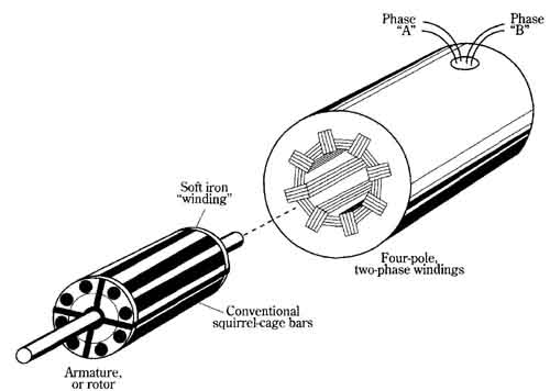
FIG. 25 An example of a reluctance synchronous motor. Components include:
Phase “A”; Phase “B”; Four-pole, two-phase windings; Conventional squirrel-cage
bars; Armature, or rotor.