AMAZON multi-meters discounts AMAZON oscilloscope discounts
..The simplest arrangement of a conventional cylindrically-shaped dc motor is shown in FIG. 19. The commutator reverses the polarity of the applied dc as the single- loop armature turns past alternate north and south magnetic poles. This ensures that torque continuously acts in the same direction. If slip rings were used, rather than a split-segment commutator, continuous rotation would not be developed from the dc source (as in the arrangement of FIG. 6). Although toy motors are made ac cording to the drawing of FIG. 19, this constructional format, though educational, exhibits at least two shortcomings, which mitigate against its consideration for practical designs.
When the single-loop armature rotates into the neutral plane, torque-producing action is lost. See FIG. 20. The commutator position is such that current through the loop is switched off. Even if such current interruption could be overcome, or greatly reduced, the relative orientation of armature and field magnetism is not proper for turning force to be exerted on the loop. What actually happens is that mechanical inertia carries the rotation of the armature loop through the neutral zone and continuous rotation does take place. Nevertheless, an undesirable situation develops because the motor will not self start if the armature loop is positioned in the a rotary switch mechanically synchronized to the position of the armature loop. Continuous rotation takes place because of reversal of armature current at appropriate times.
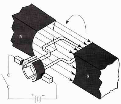
FIG. 19 Simple dc motor showing function of the commutator. The commutator
and brushes constitute neutral plane. Also, with a load, such a motor will
have a pulsating characteristic suggestive of a one or two cylinder internal
combustion engine.
A partial remedy is shown in FIG. 21 Depicted is the addition of a second loop, together with a second pair of commutator segments. The nice thing about this for mat is that the motor will always be self-starting even if one loop is in the neutral plane. Then the other loop will be in a suitable field to produce starting torque. Practical motors can have many armature loops, together with correspondingly numerous commutator segments.
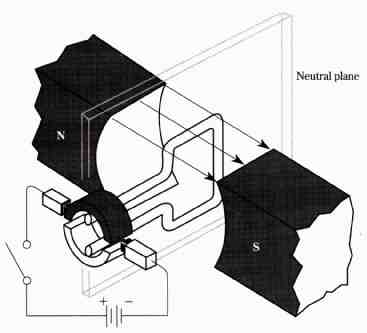
FIG. 20 The neutral plane position of the armature loop.
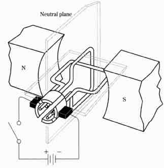
FIG. 21 The first step toward a multiconductor armature. Adding loops together
with pairs of commutator segments makes the dc motor self-starting at any shaft
position, and smoothes the torque characteristic. Neutral plane
In such practical motors, the many armature loops would be connected in series so that current would flow through more than just a single loop at a time. In this way, torque can be produced by many loops even though there are only two brushes. In such a situation, the analogy is close to that of a multicylinder engine in which smooth, nearly steady torque is developed throughout each revolution. Thus, the complete remedy to the shortcomings of the simple single-loop motor is the use of many series-connected loops.
Now, a word about the field structure is in order. Books tend to use two-pole machines to illustrate many things about motors. This is because it is simpler to draw the two-pole format, and it is less likely to confuse the reader. However, actual motors can have four, six, eight, or more poles. Multipole machines provide even more smoothening of torque. Also, multipole designs enable desirable torque levels to be had at slower speeds. This can dispense with gear boxes or belt systems in many applications.