AMAZON multi-meters discounts AMAZON oscilloscope discounts
.The Hall-effect experiment is suitable for demonstrating direct motor action on a physical object—the conducting strip itself. However, the assumption was made, even though not emphasized, that the main current through the strip was too low to produce a readily observable force. This, aside from making life easy on the battery, was the function of the current-limiting resistance, R. Here is a good example of coming very close to an important phenomenon, yet failing to discover it.
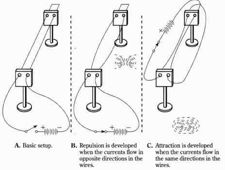
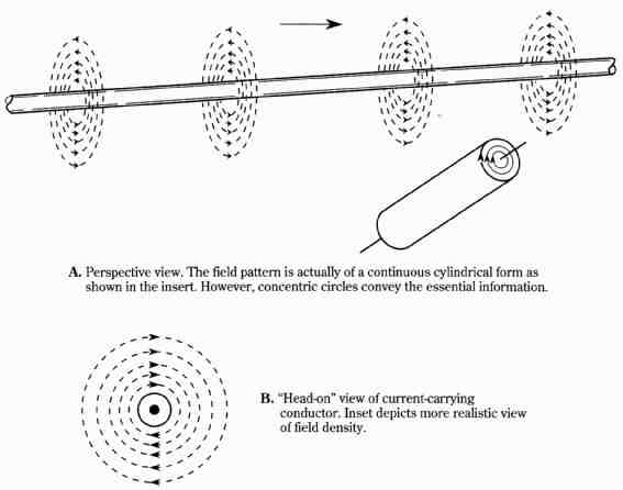
Inasmuch as experiments have indicated that interactions do exist between moving charges and magnetic fields, one could logically be led to such an experiment as that shown in FIG. 11. The rationale for the setup would be that the electric cur rent through wires involves both moving charges and magnetic fields. The magnetic field surrounds the wire in the form of circular lines of force, as depicted in FIG. 12. The lines of force are concentric and become more and more dense as the center of the wire is approached. This notation tells us that the magnetic field strength in creases as one progresses from an outside point toward the conductor.

FIG. 11 Motor-action experiments in which actual physical displacements
are produced.
A. Basic setup.
B. Repulsion is developed when the currents flow in opposite directions in the wires.
C. Attraction is developed when the currents flow in the same directions in the wires.
In FIG. 11A, the basic setup is illustrated. The parallel wires are assumed to be stranded for flexibility and to have sufficient slack in them to allow for movement. Indeed, upon closing the switch in FIG. 11B, the wires actually move apart from one another when subjected to the repulsive action of adjacent magnetic lines of force. Arid, when the current is made to flow in the same direction through both wires, as is the case in FIG. hG, the wires, impelled by attractive force, move together. The actual physical displacement of copper wires is a big leap forward from the mere displacement of charges in a vacuum, or within the confines of conducting material. Significantly, the physical movement of the wires can be interpreted by two equivalent ways of looking at the phenomena. On one hand you could deal with the interaction between the magnetic field of one wire and the moving charges of the other wire. On the other hand, you need merely consider the effects of the adjacent magnetic lines of force from each wire.
The mechanical forces responsible for the deflection of the wires do not stem from electrostatic effects. The external surfaces of the wires are neutral as far as electric fields are concerned. This can be proven by inserting a sheet of conducting material, such as aluminum, between the wires. When such “shielding” is provided, the current-dependent movements of the wires remain unaffected.
An important aspect of the current-carrying conductor is that the conductor experiences no mechanical force from its own magnetic field. This may or may not be obvious. If the current in a conductor is suddenly broken, a counter EMF is produced in the conductor from the action of its own collapsing magnetic field. Thus, a cur rent-carrying conductor in conjunction with its own magnetic field can be likened to a generator. However, motor action is only forthcoming when there is interaction be tween the current-carrying conductor and an independently produced magnetic field. The latter, however, can be produced by another portion of the conductor, as is the case in the setups of FIG. 11.

FIG. 12 The magnetic field surrounding a current-carrying conductor.
A. Perspective view. The field pattern is actually of a continuous cylindrical form as shown in the insert. However, concentric circles convey the essential information.
B. “Head-on” view of current-carrying.