AMAZON multi-meters discounts AMAZON oscilloscope discounts
OBJECTIVES
• list several factors to be considered when selecting and installing electric motor control equipment.
• explain the purpose of a contactor.
• describe the basic operation of a contactor and relay.
• list the steps in the operation of a control circuit using start and stop pushbuttons.
• interpret simple automatic control diagrams.
• draw a simple magnetic control circuit.
Motor control was a simple problem when motors were used to drive a common line shaft to which several machines were connected. In this arrangement, it was necessary to start and stop only a few times daily.
With individual drive, however, the motor is an integral part of the machine and the motor controller must be designed to meet the needs of the machine to which it's connected.
As a result, the modem motor controller does not just start, stop, and control the speed of a motor. The controller may also be required to sense a number of conditions, including changes in temperature, open circuits, current limitations, overload, smoke density, level of liquids, or the position of devices. Manual control is limited to pressing a button to start or stop the entire sequence of operations at the machine or from a remote position.
The electrician must know the symbols and terms used in automatic control diagrams to be able to wire, install, troubleshoot, and maintain automatic control equipment.
CLASSIFICATION OF AUTOMATIC CONTROLLERS
Purpose
Factors to be considered in selecting motor controllers include what types of starting, stopping, reversing, running, speed and sequence control, and protection are required.
Operation
The motor may be controlled directly or manually by an operator using a switch or a drum controller. Remote control uses contactors, relays, and pushbuttons, sensors and possibly electronics.
CONTACTORS
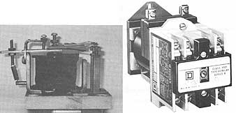
ill. 1a DC magnetic relay; ill. 1b DC operated relay.
Contactors, or relays ( 1) are required in automatic controls to transmit varying conditions in one circuit to influence the operation of other devices in the same or another electrical circuit. Relays have been designed to respond to one or more of the following conditions:
voltage current current direction power direction phase angle phase failure |
over-voltage overcurrent differential current volt-amperes power factor impedance temperature |
under-voltage undercurrent power (watts) frequency phase rotation speed |
Magnetic switches are widely used in controllers because they can be used with remote control, and are economical and safe.
A relay or contactor usually has a coil which can be energized to close or open contacts in an electrical circuit. The coil and contacts of a relay are represented by symbols on the circuit diagram or schematic of a controller. Symbols commonly used to represent contactor elements are illustrated in 2.
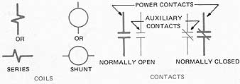
ill. 2 Schematic symbols for contactor elements.
If the control coil is connected in series in the motor power circuit, the heavy line symbol shown at the left of figure 2 is used. If the coil is connected in parallel (shunt), the light line symbol is used.
A series coil has a large current carrying conductor with few turns designed to carry large currents. A shunt coil has a small wire size with many turns; it carries small currents. It is possible for a series coil and a shunt coil to have the same ampere turns, resulting in similar magnetic results.
Contacts which are open when the coil is deenergized are known as normally open contacts and are indicated by two short parallel lines. Contacts which are closed when the coil is deenergized are called normally closed contacts and are indicated by a slant line drawn across the parallel lines.
To minimize heavy arcing which burns the contacts, a dc contactor usually is equipped with a blowout coil and an arc chute. ill 3 shows a magnetic contactor which is provided with a blowout coil and an arc chute.
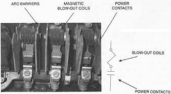
ill. 3 Magnetic blow out coils magnetically move the
arc away from the contacts: arc barriers; power contacts.
When a heavy current is broken by the contacts of the contactor, an arc occurs. ill 4 illustrates the behavior of the arc as it's quickly extinguished by the electromagnetic and thermal action of the magnetic blowout coil and arc chute.
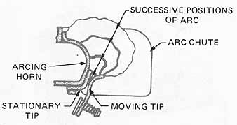
ill. 4 Behavior of arc with correctly designed blowout: ARCING
HORN; ARC CHUTE; STATIONARY TIP
PUSHBUTTONS
Pushbutton stations (figures 5A and B), are spring-controlled switches and , when pushed, are used to complete motor or motor control circuits. ill 5B shows multiple control stations, with pushbuttons, selector switches, and pilot indicating lights. Note the “mushroom” stop button for easy access. This is for convenience and safety.
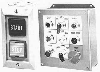
ill. 5 Pushbutton stations
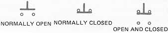
ill. 6 Symbols for pushbutton contacts: NORMALLY OPEN; NORMALLY
CLOSED; OPEN AND CLOSED
The symbols used in schematic, drawings to represent momentary pushbutton contacts are given in figure 6. Contacts can either be normally-open or normally-closed. This is the normal condition when there is no mechanical actuation of the contacts. In the pushbuttons illustrated in 6, the contacts are referred to as momentary contacts. This simply means that the contacts change from their normal condition to the opposite condition momentarily when mechanical actuation is applied, and then change back to the normal condition when the actuator is removed. Some contacts are designated as maintained contacts. This means that the contacts will stay as activated (held mechanically) until returned to their original position. See the glossary for the complete set of symbols.
TYPICAL CONTROL CIRCUIT
ill 7 is an elementary control circuit with start and stop buttons and a sealing circuit. The following sequence describes the operation of the circuit. The typical control circuit uses an electromagnetic coil to move sets of contacts. The contacts move to open and close the power circuit to the motor, and also open and close contacts in the control circuit. The control contacts provide a sealing circuit in parallel to the start momentary contacts. This parallel circuit's referred to as the sealing circuit. It seals a current path around the normally open start button contacts. The circuit operation is as follows:
1. When the start button is pressed to close contacts 2-3, current flows from L1 through normally closed contacts 1 - 2 of the stop button, through the closed contacts 2 - 3 of the start button, and through coil M to Line L2.

ill. 7 A control circuit with start and stop buttons and sealing circuit
2. The current in coil M causes the contact M to close. Thus, the sealing circuit around contacts 2-3 of the start button closes. The start button may now be released, and even though the spring of the pushbutton opens contacts 2-3, coil M remains energized and holds contacts M closed to maintain a sealing circuit around the normally open contacts 2-3 of the start button. Coil M, being energized, also closes M contacts in the power circuit to the motor (not shown).
3. If the stop button is momentarily pressed, the circuit's interrupted at contacts 1 - 2 and coil M is deenergized. Contacts M then open and coil M cannot be energized until the start button again closes contacts 2 - 3.
SUMMARY
The basic automatic control circuit's used to control larger motors and to control them through electromagnetic relays. This allows the operation to be remotely located and the contactor to be located near the motor. The basic principle uses a momentary-contact switch to close a circuit to a magnetically-operated relay.
QUIZ
Select the correct answer for each of the following statements.
1. Early motor installations consisted of:
a. individual drives.
b. a common line shaft drive.
c. automatically controlled motor drives.
d. remotely controlled motors.
2. Individual motor drives require:
a. single-phase motors.
b. automatic controllers.
c. speed rheostats.
d. gear heads.
3. Automatic dc motor controllers are designed to respond to changes in temperature, open circuits, current limitations, and :
a. wire size. c. speed acceleration.
b. fuse rating. d. brush assembly.
4. Interpretation of automatic control circuits requires the recognition of:
a. color. c. ratings
b. electrical circuit symbols. d. parallel circuits
5. A relay symbol shows the:
a. number of turns in a coil.
b. relay current rating.
c. relative position of the component parts.
d. size of the contacts.
6. A relay is classified as a piece of electrical equipment with at least one:
a. coil.
b. resistor.
c. coil operating one contact.
d. coil operating two contacts.
7. Normally open contacts are
a. open at all times.
b. open when the relay coil is deenergized.
c. open when the relay coil is energized.
d. contacts that open a circuit.
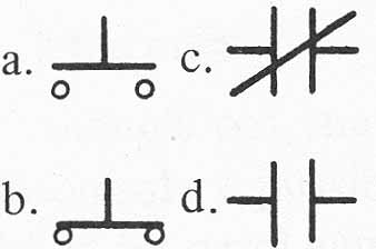
8. Normally closed relay contacts are represented by the symbol:
9. A sealing circuit bypasses:
a. the armature circuit.
b. the field circuit.
c. the ON pushbutton contacts.
d. the relay coil.
10. Elementary control diagrams are read from:
a. top to bottom. c. right to left.
b. bottom to top. d. Field to armature circuit.