AMAZON multi-meters discounts AMAZON oscilloscope discounts
OBJECTIVES
• list the primary functions of the three-terminal starting rheostat and the four-terminal starting rheostat.
• demonstrate the proper connection and startup procedure for a three-terminal starting rheostat on a shunt motor and on a cumulative compound-wound motor.
• demonstrate the proper connection and startup procedure for a four-terminal starting rheostat on a shunt motor and on a cumulative compound-wound motor.
• state basic dc motor starting principles common to other motor starters.
Manual starting rheostats for dc motors are becoming more and more rare. Electronic controls have replaced the manual three-point and four-point controllers for dc motor starters. However, three-point and four-point controllers are still being used, so the maintenance electrician should know the principles of operation of the manual dc starters.
Two factors limit the current taken by a motor armature from a direct-current source:
(1) the counter electromotive force, and (2) the armature resistance. Since there is no counter emf when the armature is at a standstill, the current taken by the armature will be abnormally high. As a result, the armature current must be limited by an external resistor, such as a starting rheostat. Electric Motor Control covers in detail this method of limiting armature current.
A starting rheostat or motor starter is described by the National Electrical Manufacturers’ Association as a device designed to accelerate a motor to its normal rated speed in one direction of rotation. In addition, a motor starter limits the current in the armature circuit to a safe value during the starting or accelerating period. Two types of manual starting rheostats are:
• three-terminal starting rheostat, and
• four-terminal starting rheostat.
The electrical technician is expected to know how each type of starting rheostat is connected to direct-current shunt and compound motors. The technician should also know the specific applications and limitations of each type of motor starter.
THREE-TERMINAL STARTING RHEOSTAT
The three-terminal starting rheostat has a tapped resistor enclosed in a ventilated box. Contact buttons located on a panel mounted on the front of the box are connected to the tapped resistor. A movable arm with a spring reset can be moved over the contact buttons to cut out sections of the tapped resistor.
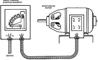
The connection diagram for a typical three-terminal starting rheostat is illustrated in 1. Note that the starter has three terminals or connection points and that it's connected to a shunt motor.
When the arm of the rheostat is moved to the first contact, A, the armature (which is in series with the starting resistance) is connected across the source. The shunt field, in series with the holding coil, is also connected across the source. The initial current inrush to the armature is limited to a safe value by the starting resistance. In addition, the shunt field current is at a maximum value and provides a good starting torque.
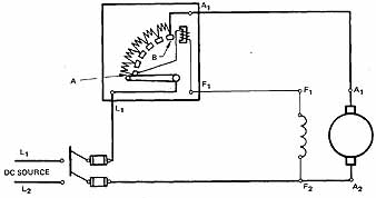
ill. 1: Connections for a three-terminal starting rheostat.
As the arm is moved to the right toward contact B, the starting resistance is reduced and the motor accelerates to its rated speed. When the arm reaches contact B, the armature is connected directly across the source voltage, and the motor will have attained full speed.
The holding coil is connected in series with the shunt field and provides a no-field release. If the shunt field opens, the motor speed will become dangerously high if the armature circuit remains connected across the source. Therefore, in the event of an open-circuited shunt field, the holding coil of the starting rheostat becomes demagnetized and the arm returns to the off position.
Note that the starting resistance is in series with the shunt field when the arm is in the run position at contact B. This additional resistance has practically no effect on the speed as the starting resistance is small when compared with the shunt field resistance.
To operate a three-terminal starter, first close the line switch. Then, move the starting arm from the off position to contact A. Continue to move the arm slowly toward contact B, pausing on each intermediate contact for a period of one to two seconds. By moving the arm slowly toward the run position at contact B, the motor will accelerate uniformly to its rated speed without an excessive inrush of current to the armature. How ever, don't hold the arm on any one contact between A and B for too long a period of time. These starting resistors are designed to carry the starting current for a short period of time only. In other words, don't control the speed of the motor by holding the arm for any length of time on any contact between A and B.
If it's necessary to control the speed of the motor, don't use a three-terminal starter. Since the current in the shunt field and holding coil may be reduced to a value insufficient to hold the arm against the action of the reset spring, the reset spring will return the arm to the off position. Thus, the motor will become disconnected from the cur rent source.
When a motor is to be disconnected from the current source, first open the line switch quickly. Then, check to see that the spring reset returns the starting arm to the off position.
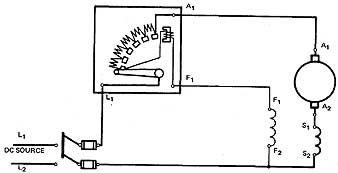
ill. 2 Three-terminal starting rheostat connected to a cumulative
compound-wound motor.
ill 2 shows the connections for a three-terminal starting rheostat used with a cumulative compound-wound motor. Note that these connections are almost the same as those of a three-terminal starting rheostat connected to a shunt motor; the only change in figure 2 is the addition to the motor of the series field.
FOUR-TERMINAL STARTING RHEOSTAT
A four-terminal starting rheostat performs the same functions as a three-terminal starting rheostat:
• it accelerates a motor to rated speed in one direction of rotation.
• it limits the starting surge of current in the armature circuit to a safe value.
In addition, the four-terminal starting rheostat may be used where a wide range of motor speeds is necessary. A field rheostat may be inserted in series with the shunt field circuit to obtain the desired speed.
ill 3 shows a four-terminal starting rheostat. Note that the holding coil isn't connected in series with the shunt field as it's in the three-terminal starting rheostat. The holding coil in figure 3 is connected in series with a resistor across the source. Note also that the holding coil circuit's connected across the source and , as a result, four terminal connection points are necessary.
The holding coil of the rheostat is connected across the source and acts as a no voltage release. E.g., if the line voltage drops below the desired value, the attraction of the holding coil is decreased, and the reset spring will then return the arm to the off position.
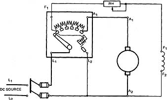
ill. 3 Connections for a four-terminal starting rheostat
When a four-terminal starting rheostat is used, the speed of the motor is controlled by varying the resistance of the field rheostat connected in series with the shunt field circuit. The speed is increased above the rated speed by inserting resistance in the field rheostat.
When a motor using a four-terminal starting rheostat is to be disconnected from the source, first cut out all resistance in the field rheostat. Then, open the line switch and check to see that the spring reset returns the starting arm to the off position.
By removing all resistance from the field rheostat, the strength of the shunt field is increased. Thus, when the motor is restarted, it will have a strong field and strong starting torque.
ill 4 shows a four-terminal starting rheostat connected to a cumulative com pound-wound motor. Note the similarity in connections for a shunt motor ( 3) and a compound-wound motor ( 4). The only change in figure 4 is the addition of the series field.
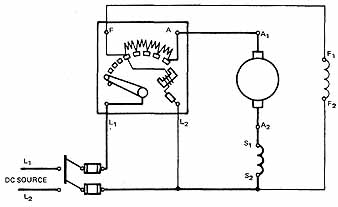
ill. 4 Four-terminal starting rheostat connected to a cumulative
compound-wound motor.
NATIONAL ELECTRICAL CODE RULES FOR MOTOR STARTERS
The National Electrical Code states that a motor starter shall be marked with voltage and horsepower ratings, and the manufacturer’s name and identification symbols, such as style or type numbers.
Electrical codes require that the horsepower rating of a starter must not be smaller than the horsepower rating of the motor. In addition, the fuse protection for dc motors must be no greater than a percentage of the full-load current rating of the motor. There fore, the motor starter must limit the starting current to a value which is no greater than a percentage (specified by the electrical code) of the full-load current rating of the motor.
It is recommended at this time to review the National Electrical Code section on motors, motor circuits, and controllers.
SAFETY PRECAUTIONS FOR DC MOTOR STARTERS
Current must be limited when starting the armature. A no-field release is provided to prevent runaway acceleration.
To operate a three- or four-terminal starter, the starting arm is moved slowly, pausing for one or two seconds only before moving to the next position.
Three-Terminal Starter
To decelerate the motor, first open the line switch. Check the starting arm and return it to the OFF position by using the reset spring.
Four-Terminal Starting Rheostat
Decelerate the motor by cutting out all resistance in the field rheostat. Open the line switch. Check the starting arm and return it to the OFF position by using the reset spring.
SUMMARY
Three-terminal and four-terminal starting rheostats are not used too much any more. The advent of electronic starters have all but replaced the mechanical starters. The concept of the starter is still used and the safeguards for motor operation are still important.
QUIZ
1. What are the two functions of a motor starter?
a. __
b. __
2. Show the connections of a three-terminal starting rheostat to a shunt motor.
3. State one advantage of a three-terminal starting rheostat.
4. Name one limitation of a three-terminal starting rheostat.
5. Complete the connections in the following figure to show the shunt motor properly connected to the three-terminal starting rheostat.
7. What is one advantage of a four-terminal starting rheostat?
6. Show the connections of a four-terminal starting rheostat to a shunt motor.
8. List the items that should be marked on the nameplate of a motor starter to comply with National Electrical Code requirements.
9. Complete the connections in the following figure to show that the cumulative com pound-wound motor can be started from the four-terminal starting rheostat. Also connect the field rheostat in the circuit for above-normal speed control.
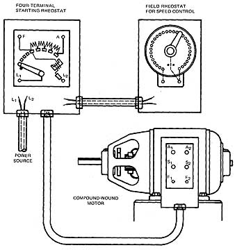
FOUR-TERMINAL STARTING RHEOSTAT; FIELD RHEOSTAT FOR SPEED CONTROL; COMPOUND-WOUND MOTOR
10. What is the full-load current rating of a hp, 240-V motor? (Refer to the National Electrical Code, if necessary.)
11. What size conduit's required between the hp motor and the starting box, using type THHN wire?