AMAZON multi-meters discounts AMAZON oscilloscope discounts
OBJECTIVES
• perform routine inspection and maintenance checks of three-phase motors.
• perform the following simple tests:
- measure insulation resistance
- use a growler to locate short-circuited coils continuity checks for open-circuited coil
- balance test to determine phase currents under load speed variation
• replace and lubricate sleeve and ball bearings, according to manufacturers’ directions.
• lubricate motors, according to manufacturers’ directions.
PREVENTIVE MAINTENANCE
Most electrical equipment requires planned inspection and maintenance to keep it in proper working condition. Periodic inspections prevent serious damage to machinery by locating potential trouble areas. Observant personnel will make full use of their senses to diagnose and locate problems in electrical machinery: the sense of smell directs attention to burning insulation; the sense of touch detects excessive heating in windings or bearings; the sense of hearing detects excessive speed or vibration; the sense of sight detects excessive sparking and many mechanical faults.
Sensory impressions usually must be supplemented by various testing procedures to localize the trouble. A thorough understanding of electrical principles and the efficient use of test equipment is important to the electrician in this phase of troubleshooting.
PERIODIC INSPECTIONS
The ideal motor maintenance program aims at preventing breakdowns rather than repairing them. Systematic and periodic inspections of motors are necessary to ensure best operating results. In a good preventive maintenance program with detailed checks, the person in charge should have a record card on file for every motor in the plant. Entries on the card should include inspection dates, descriptions of repairs, and the costs involved. When the record indicates that a motor has undergone excessive and /or costly repairs, the causes can be determined and corrected.
Inspection records also serve as a guide to indicate when motors should be replaced because of their high cost of operation. They also reveal faulty operating conditions, such as misapplication or poor drive engineering.
Inspection and servicing should be systematic. However, the frequency of inspections and the degree of thoroughness may vary, as determined by the plant maintenance engineer. Such determinations are based on 1) the importance of the motor in the production scheme (if the motor fails, will production be slowed seriously, or stopped?), 2) the percentage of the day the motor operates, 3) the nature of the service, and 4) the motor’s environment. An inspection schedule, therefore, must be flexible, and adapted to the needs of each plant. Equipment manufacturers’ specifications and procedures should be consulted and followed.
The following schedule, which covers both ac and dc motors, is based on average conditions insofar as operational use and cleanliness are concerned. (Where dust and dirty conditions are extremely severe, open motors may require a certain amount of cleaning every day.)
EVERY WEEK
1. Examine commutator and brushes, ac and dc.
2. Check oil level in bearings.
3. See that oil rings turn with shaft.
4. See that exposed shaft is free of oil and grease from bearings.
5. Examine the starter switch, fuses, and other controls; tighten loose connections.
6. See that the motor is brought up to speed in normal time.
EVERY SIX MONTHS
1. Clean motor thoroughly, blowing out dirt from windings, and wipe commutator and brushes.
2. Inspect commutator clamping ring.
3. Check brushes and replace any that are more than half worn.
4. Examine brush holders, and clean them if dirty. Make certain that brushes ride free in the holders.
5. Check brush pressure.
6. Check brush position.
7. Drain, wash out, and replace oil in sleeve bearings.
8. Check grease in ball or roller bearings.
9. Check operating speed or speeds.
10. See that end play of shaft is normal.
11. Inspect and tighten connections on motor and control.
12. Check current input and compare it with normal.
13. Examine drive, critically, for smooth running, absence of vibration, and worn gears, chains, or belts.
14. Check motor foot bolts, end-shield bolts, pulley, coupling, gear and journal set screws, and keys.
15. See that all covers, and belt and gear guards are in place, in good order, and securely fastened.
ONCE A YEAR
1. Clean out and renew grease in ball or roller bearing housings.
2. Test insulation by megohmmeter.
3. Check air gap.
4. Clean out magnetic dirt that may be clinging to poles.
5. Check clearance between shaft and journal boxes of sleeve bearing motors to pre vent operation with worn bearings.
6. Clean out undercut slots in commutator. Check the commutator for smoothness.
7. Examine connections of commutator and armature coils.
8. Inspect armature bands.
MEASUREMENT OF INSULATION RESISTANCE
The condition of insulation is an important factor in the maintenance of motors and alternators. Moisture, dirt, chemical fumes, and iron particles all cause deterioration of the insulation used on the windings of stators and rotors. Motors operating under adverse conditions require periodic tests to insure continuous and satisfactory operation. Although severe conditions can be detected by touch, sight, or smell, often it's necessary to use more accurate measures of the condition of insulation at any given time.
The value of insulation resistance in megohms (1,000,000 ohms) is used as an indication of insulation efficiency. Successive readings taken and recorded under the same test conditions will document the insulation history of a unit and will serve as an index of insulation deterioration. A megohmmeter, commonly called a Megger ( 1A and B) is used to measure insulation resistance. In general, the instrument develops a volt age which is applied to the insulation path. The amount of current in this path is shown on a sensitive microammeter calibrated in megohms. When the instrument leads are not connected, the microammeter reading should be infinity. Specific operating instructions are provided with the instrument by the manufacturer.
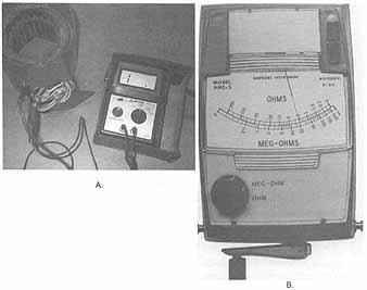
ill. 26-1 A) Connections for testing motor winding resistance
to the motor frame B) Megohmmeter used with hand crank operation.
The megohmmeter ground lead is connected to the frame of the machine. The ungrounded lead is connected to any metallic part of the winding being tested, such as any terminal of the coil circuit. No other external paths must exist in parallel circuits. For this reason, the windings being tested should be isolated by disconnecting them from other parts of the circuit. The megohmmeter reading then is the resistance of the insulation between the number of coils in the circuit and the frame of the machine.
Major motor manufacturers apply insulation resistance for 660 volts for low-voltage motors below 600 volts. A method of determining the normal insulation resistance value is given in the following formula. It is a non-exact formula derived from experience. It is believed that the Institute of Electrical and Electronic Engineers, Inc. (IEEE) accepted this general theory from a manufacturer of megohmmeters.
Caution: Disconnect electronic devices attached to units under test.
Megohms = Rated Voltage of Machine /((Rating in kVA/100) + 1000)
A very low value of insulation resistance indicates defective insulation. The electrician should begin an immediate check to localize the defective insulation. This is done by disconnecting various coils from a series, parallel, wye, or delta combination and repeating the insulation resistance test on each isolated coil. A very low value of resistance may indicate a grounded coil (complete breakdown of insulation at some point).
A value of insulation resistance slightly below the recommended approximate value does not necessarily indicate that immediate repair is required. The electrician should take a series of readings at weekly intervals to detect any progressive decrease or sudden drop in the insulation resistance. If the resistance continues to decrease, then the fault is to be located without delay. A slightly low but constant value of resistance shouldn't cause concern. NOTE: If a motor has been reading 10 megohms on periodic tests and suddenly drops to 0.2 megohms, the motor may be unsafe to start. New motors read around infinity (the highest resistance on the meter scale), or slightly lower, but, during use, this resistance lowers to a more steady reading.
TESTING FOR SHORT-CIRCUITED COILS
Open-circuited coils on rotors or stators can be located by continuity (one end to the other) tests. Short-circuited coils are located easily by the use of a growler. A growler is an instrument consisting of an electromagnetic yoke and winding excited from an ac source. The yoke is placed across a section of slots containing the winding being tested. The yoke winding acts as the primary winding of a transformer and the winding being tested acts as the secondary ( 2).
If a turn or coil is short circuited, the resulting current rise in the primary (yoke) circuit's indicated on the ammeter. If the current is permitted to exist for a short period of time, the defective turn or coil can be identified by the heat developed at the defective point. The stator windings of both alternators and motors can be tested by this method.
The field coils of alternators can be tested using the voltage drop method described for dc machinery testing. With a given value of current in the field circuit, the voltage drops on individual field coils should be approximately equal. If there is a voltage drop difference in excess of 5 percent, the coil should be investigated for shorted turns. The presence of full line voltage across a single coil indicates an open circuit in that coil.
The field coils of alternators can be checked for impedance by applying a high frequency low voltage to each coil and measuring the current. The currents in the coils should be equal. The presence of a high current usually means that there are shorted turns somewhere in the coil.
BALANCE TEST
The current in the individual phases of three-phase motors must be equal. ill 3 shows the connections necessary to make a simple balance test which measures the phase currents under load. This test may be made in the electric shop before a motor is installed.
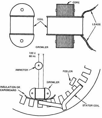
ill. 2 A growler for testing shorted coils.
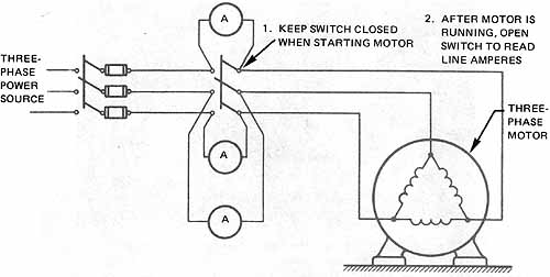
ill. 3 A balanced current motor test.
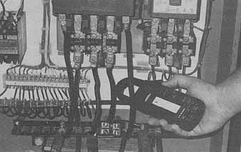
ill. 4 Use of clamp-on ammeter to test motor power system.
The fused three-pole switch at the left of the diagram is used to start the motor. The second three-pole switch removes the ammeter from the circuit during the starting period when the current input is very high. This switch is closed before the motor is started. When the motor reaches its rated speed, the ammeter switch is opened. The current in each phase, therefore, is indicated on the ammeter. For a motor operating normally, the three line currents are equal. A high reading in one phase may indicate shorted turns. If one phase shows no current, then the motor is operating as a single-phase motor. High but equal current readings in all three phases indicate an overloaded motor.
ill 26-4 shows the use of a more convenient method of making a balance test. A clamp-on ammeter is used to take readings in each phase of a motor in actual operation under normal load.
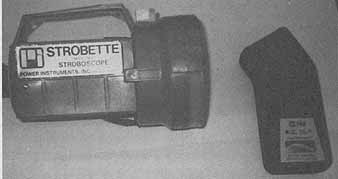
ill. 5 Strobe tachometer and a photo reflective tachometer
MEASUREMENT OF SPEED VARIATIONS
Deviations from the rated speed of a motor under load are an indication of improper mechanical loading or faulty conditions within the motor. A tachometer (figures 26-5 and 26-6) is an instrument used to check the speed of a motor. Other types of instruments are also used. The tachometer in figure 6 is held by hand to the end of the motor shaft to measure shaft speed.
SQUIRREL CAGE ROTORS
The bars of a squirrel-cage rotor can be broken if the motor is subjected to severe jarring, vibration, or overheating. Bars that are dislodged must be put back in place securely so that movement is impossible. The presence of broken bars can be detected by the use of a growler. (The rotor must be removed to make this test.)
A test can be made which does not require the removal of the rotor to detect broken or open rotor bars. This test consists of exciting one phase of the stator winding with 25 percent of its normal voltage. Enough voltage is used to give a suitable indication on an ammeter in series with the winding. By turning the rotor slowly by hand, any variations in stator current can be observed on the ammeter. Any current variation in excess of 3 per cent usually indicates open bars in the rotor (ill 26-7).
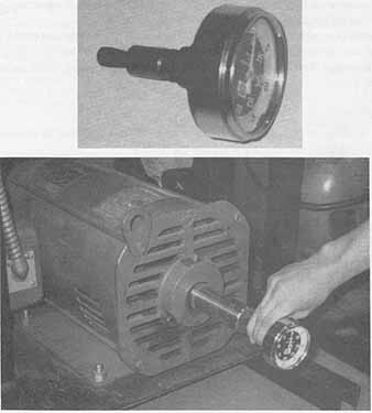
ill. 6 Mechanical tachometer used to measure shaft RPM.
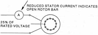
ill. 7 An ammeter used to test for open rotor bars In a squirrel
cage rotor.
BEARINGS
The type of bearings used in a motor depends on the cost of the motor and the characteristics of the load. Sleeve and ball bearings are used in both ac and dc motors. Excessive wear on the bearings reduces the concentricity of the stator and rotor sections. In small motors, with the power off, excessive wear can be detected by manually attempting to move the shaft of the rotating member in a lateral direction. The amount of play in the shaft is an indication of bearing wear. For large motors, bearing wear and the resulting deviation in concentricity of the stator and rotor can be detected by measuring the air gaps over several points around the periphery of the rotor. Severe bearing wear on both large and small motors may result in actual contact between the rotor and the stator.
The motor must be disassembled to repair bearings. This type of repair requires special tools and the job shouldn't be attempted without them.
A sleeve bearing is removed by dismantling the baffles inside the end shield, removing the oil well cover plates, and removing the oil ring clips. The bearing lining is then tapped out using a short length of pipe stock or a special split fitting which locks inside the oil ring slot.
Ball Bearings
Ball bearings are press fitted to the motor shaft and usually should be removed from the shaft only when it's necessary to replace the bearing.
To inspect the ball bearings, the end bells are removed and the rotor, the rotor shaft, and the bearing assembly are taken from the stator. In some motors, the bearing housings have removable bearing caps so that it's possible to remove the bearing without removing the end bells.
If a ball bearing must be replaced, a bearing puller usually is used to prevent damage to the shaft. The electrician must be very careful when placing a new bearing on the shaft so that neither the bearing nor the shaft is damaged ( 8). A ball bearing race must be placed on the shaft so that the race is exactly square with the shaft. The shaft must be in perfect condition since even the slightest burr will cause trouble. Pressure must not be applied to the outer race of the bearing. Pressure applied to install the bearing must be applied evenly on the diameter of the inner race ( 9). Light tapping is recommended. A piece of pipe stock slightly greater than the shaft diameter is used to press on the new bearing. The bearing can be warmed to a temperature of 150° F to simplify the process.
New ball bearings must not be cleaned prior to installation. Dust or dirt must not enter the bearing during the installation.
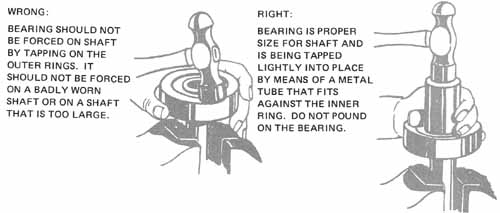
ill. 8 Bearing Installation: wrong: bearing shouldn't be forced on shaft by tapping on the outer rings. It shouldn't be
forced on a badly worn shaft or on a shaft that's too large. Right:
bearing is proper size for shaft and is being tapped lightly into place
by means of a metal tube that fits against the inner ring. Don't pound
on the bearing.
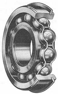
ill. 9 Single-row, snap ring ball bearing.
LUBRICATION
Several methods of lubricating motors are used. Small motors with sleeve bearings have oil holes with spring covers. These motors should be oiled periodically with a good grade of mineral oil. Oil with a viscosity of 200 seconds Saybolt (approximately SAE 10) is recommended.
The bearings of larger motors often are provided with an oil ring which fits loosely in a slot in the bearing. The oil ring picks up oil from a reservoir located directly under the ring. Under normal operating conditions, the oil should be replaced in the motor at least once a year. More frequent oil replacement may be necessary in motors operating under adverse conditions. In all cases, avoid excessive oiling; insufficient oil can ruin a bearing but excessive oil can cause deterioration of the insulation of a winding.
Many motors are lubricated with grease. Periodic replacement of the grease is recommended. In general, the grease should be replaced whenever a general overhaul is indicated, or sooner if the motor is operated under severe operating conditions.
Grease can be removed by using a light mineral oil heated to 165° F or a solvent. Any grease-removing solvents should be used in a well-ventilated work area.
Ball Bearing Lubrication
The following table indicates recommended intervals between the re-greasing of ball bearing units. It is important that the correct amount and type of grease be used in ball bearings. Too much grease can cause overheating.
Fractional horsepower motors often contain sealed bearings. With normal service, these bearings don't require regreasing. When regreasing is required for unshielded bearings, the manufacturers’ specifications and directions must be followed.
Some motors with ball bearings are provided with pressure fittings and a grease gun is used to lubricate the bearings. Remove the bottom plug when doing this. Because of the wide variation in the design of industrial motors, the electrician should consult the comprehensive lubrication manuals published by electrical machinery manufacturers to insure the proper lubrication of all types of motors.
BALL AND ROLLER BEARING MAINTENANCE
Cleaning Out Old Grease
It is best to remove the bearing, if possible. However, when cleaning a bearing in place, remove as much of the old grease as possible, using a rag or brush free from dirt or dust. Flush out the housing with clean, hot kerosene (110 F to 125° F); clean, new oil; or solvent.
After the grease has been removed, flush out the bearing with light mineral oil to prevent rust and to remove all traces of cleaning fluid. Allow to drain thoroughly before adding new grease.
When the bearing is removed from the case, wash out the hardened, rancid grease from the housing and bearing as follows:
1. Put on safety glasses, or a face shield, for protection.
2. Soak the bearing in hot kerosene, then remove it.
3. Rotate the bearing slowly by air hose. (Fast rotation may score the balls without lubrication.)
4. Dip the bearing in clean kerosene, light oil, or solvent.
5. Rotate the bearing slowly again by air hose.
6. Wash the bearing again with clean kerosene or solvent.
7. Rotate the bearing in hand, and check for smoothness.
8. If the bearing is smooth, repack it with grease.
9. If the bearing isn't smooth, but is in good condition, there is still some hardened grease in it. Repeat operations 6 and 7.
Lubricating Bearings with Pressure Relief Plug
1. Wipe fitting and plug clean.
2. Remove relief plug in bottom of bearing ( 10).
3. With shaft in motion (if possible), force grease into the top grease fitting, catching old grease in a pan. Add grease until new grease appears at the pan.
4. With a screwdriver, open the relief hole. Don't push the screwdriver into the gearing housing.
5. Allow bearing to run with relief plug out to remove pressure.
6. After the grease stops running out, and there is no longer any pressure in the bearing, replace the relief plug.
Lubricating Bearings without Relief Plug
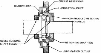
ill. 10 Ball bearing housing assembly. Note the lubrication
inlet and outlet
1. Install a grease fitting with safety vents.
2. With the motor running, pump in grease slowly until a slight bleed shows around the seal or safety vent.
3. If necessary to lubricate while bearing is standing, fill the bearing with grease from one-fourth to one-half of its capacity.
NOTE: It is important not to overgrease, and grease must be kept clean.
Re-lubrication with Oil
Oil is always subject to gradual deterioration from use, and contamination from dirt and moisture. Because of this, regular intervals for cleaning bearings must be maintained.
1. After draining the used oil, flush out the bearing. This can be done by using a new charge of the lubricant used for regular lubrication. Run the machine for three to five minutes, and drain again. Units used where there is sawdust or dirty conditions may require two flushings.
2. Fill with new oil to the proper level. Be sure new oil is from a clean container, and that no dirt is pushed into the filler plug while filling. Lubricant must be kept clean.
3. Check the seals to see that they are effective to prevent leakage or the entry of out side dirt to the bearing. It is important to keep the lubricant clean and the bearing flushed out so that it will be clean. Always read and follow the manufacturer’s instructions whenever possible.
OILS FOR GEAR MOTORS
A gear motor is a self-contained drive made up of a ball bearing motor and a speed reducing gear box. It is designed to take advantage of the electrical efficiency of the high speed motor and the transmission efficiency of gears.
The front motor bearings are generally grease lubricated and require the same attention as standard ball bearing motors. The rear bearings, gear box bearings, and the gears themselves are almost always splash lubricated from the same oil supply reservoir in the lower section of the gear unit.
Oil seals at each bearing prevent oil leakage into the motor windings and out along the drive shaft. The precision cut gears require carefully selected lubricating oils. Use only top grade oils of the viscosity called for by the manufacturer of the gear motor.
SUMMARY
Proper motor maintenance will extend the life of the motor. Preventive maintenance will help you spot potential problems and correct them before the motor breaks down and causes delays in productions or failures at critical times. If a motor does fail, it may be possible to repair minor problems in the maintenance shop and to recondition the motor for use as a spare. Follow manufacturers directions when lubricating the motor bearings to keep the motor running smoothly without excessive current draw or excessive heat. Check for proper ventilation, proper voltage and proper current when performing maintenance checks on the motor.
REVIEW QUIZ
A. Select the correct answer for each of the following statements and place the corresponding letter in the space provided.
1. Periodic inspection of motors, controls, and other electrical equipment is important because it:
a. gives advance notice of impending trouble.
b. is required by the job standards.
c. is a requirement of supervision.
d. completes a day’s work.
2. Careful motor troubleshooting requires the use of:
a. the sense of smell c. hearing and vision. b. the sense of touch d. all of these.
3. The most accurate method of testing insulation resistance uses a(an)
a. megohmmeter. c. ohmmeter. b. growler d. tachometer.
4. Insulation resistance is measured in
a. megawatts. c. k-ohms. b. megohms. d. kilovolts.
5. A very low value of insulation resistance indicates
a. a good operating condition.
b. a fair operating condition.
c. an immediate investigation.
d. that the measuring instrument is at the wrong setting.
6. Short-circuited coils are located efficiently by the use of a(an) a. megohmmeter. c. ohmmeter.
b. growler. d. clamp-on ammeter.
7. On a balance test for phase currents where one phase shows a higher reading, the probable cause is:
a. open turns.
b. shorted turns.
c. worn bearings.
d. the need for rotor balancing.
8. If a three-phase, squirrel-cage motor is operating with current in only two line leads, then:
a. the motor is operating as a two-phase motor.
b. the insulation is overloaded.
c. there is an open circuit in the stator.
d. there is an open circuit in the rotor.
9. A properly-sized ball bearing race is mounted on a shaft correctly by tapping:
a. a metal tube on the outer ring.
b. the inner ring with a hammer.
c. the outer ring with a hammer.
d. a metal tube on the inner ring.
10. A ball-bearing, ten-hp, three-phase, 230-volt induction motor operating under very severe conditions should be greased about every
a. three months. c. twelve months.
b. six months. d. month.
B. Insert the word or phrase to complete each of the following statements.
11. The instrument used to measure insulation resistance is operated with the test leads unconnected. The meter reading should be ______.
12. The measurement of individual phase currents in the operation of a three-phase induction motor is called a(an) ____.
13. The rotor and stator concentricity in three-phase motors and alternators can be deter mined by measurements of the _____________
14. Ball bearings should be removed from a motor shaft using a bearing
15. Pressure should never be applied to the __________ race of a ball bearing.
16. Ball bearings are lubricated with __________.
17. Insufficient oil can ruin a bearing, but excessive oiling can ruin the _________.