AMAZON multi-meters discounts AMAZON oscilloscope discounts
OBJECTIVES
• describe the basic operation of a universal motor.
• explain how a single-field compensated universal motor operates.
• explain how a two-field compensated universal motor operates.
• describe two ways in which universal motors are compensated for excessive armature reaction under load.
• state the reasons why dc motors fail to operate satisfactorily from an ac source.
The electrician may consider a typical dc series motor or a dc shunt motor for operation on ac power supplies. It appears that such operation is possible since reversing the line terminals to a dc motor reverses the current and magnetic flux in both the field and armature circuits. As a result, the net torque of the motor operating from an ac source is in the same direction.
However, the operation of a dc shunt motor from an ac source is impractical because the high inductance of the shunt field causes the field current and the field flux to lag the line voltage by almost 90 degrees. The resulting torque is very low.
A dc series motor also fails to operate satisfactorily from an ac source because of the excessive heat developed by eddy currents in the field poles. In addition, there is an excessive voltage drop across the series field windings due to high reactance.
To reduce the eddy currents, the field poles can be laminated. To reduce the voltage loss across the field poles to a minimum, a small number of field turns can be used on a low reluctance core operated at low flux density. A motor with these revisions operates on either ac or dc and is known as a universal motor. Universal motors in small fractional horsepower sizes are used in household appliances and portable power tools.
CONCENTRATED FIELD UNIVERSAL MOTOR
A concentrated field universal motor usually is a salient-pole motor with two poles and a winding of relatively few turns. The poles and winding are connected to give opposite magnetic polarity. A field yoke of this type of motor is illustrated in 1.
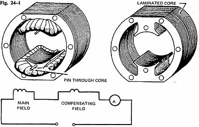
ill. 1 Field core of a two-pole universal motor. ill. 2 Schematic
diagram of a compensated universal motor
DISTRIBUTED FIELD UNIVERSAL MOTORS
The two types of distributed field universal motors are: the single-field compensated motor and the two-field compensated motor.
The field windings of a two-pole, single-field compensated motor resemble the stator winding of a two-pole, split-phase ac motor. A two-field compensated motor has a stator containing a main winding and a compensating winding spaced 90 electrical degrees apart. The compensating winding reduces the reactance voltage developed in the armature by the alternating flux when the motor operates from an ac source. ill 2 is the schematic diagram of a compensated universal motor.
THE ARMATURE
The armature of a typical universal motor resembles the armature of a typical dc motor except that a universal motor armature is slightly larger for the same horsepower output.
CONSTRUCTION FEATURES OF UNIVERSAL MOTORS
The frames of universal motors are made of aluminum, cast iron, and rolled steel. The field poles are generally bolted to the frame. Field cores consist of laminations pressed together and held by bolts. The armature core is also laminated and has a typical commutator and brushes. End plates resemble those of other motors except that in many universal motors one end plate is cast as part of the frame. Both ball and sleeve bearings are used in universal motors.
SPEED CONTROL
Universal motors operate at approximately the same speed on dc or single-phase ac. Since these motors are series wound, they will operate at excessive speed at a no-load condition. As a result, they usually are permanently connected to the devices being driven. Universal motors are speed regulated by inserting resistance in series with the motor. The resistance may be tapped resistors, rheostats, or tapped nichrome wire coils wound over a single field pole. In addition, speed may be controlled by varying the inductance through taps on one of the field poles. Gear boxes are also used.
Speed control of series motors can also be accomplished by using electronic speed controls. The concept is the same as used series voltage drops; that's , the voltage to the motor is reduced to give a reduced speed. This can be done by using SCRs or triacs to alter the voltage available to the motor.
DIRECTION OF ROTATION
The direction of rotation of any series wound motor can be reversed by changing the direction of the current in either the field or the armature circuit. Universal motors are sensitive to brush position and severe arcing at the brushes will result from changing the direction of rotation without shifting the brushes to the neutral (sparkless) plane, or adding a compensating winding.
CONDUCTIVE COMPENSATION
Ac motors rated at more than 1/2 horsepower are used to drive loads requiring a high starting torque. Two methods are used to compensate for excessive armature reaction under load. In the conductively compensated type of motor, an additional compensating winding is placed in slots cut directly into the pole faces. The strength of this field increases with an increase in load current and thus minimizes the distortion of the main field flux by the armature flux (called armature reaction-discussed in DC Motor Unit-).
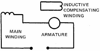
ill. 3 Connections for an inductively compensated universal
motor.
The compensating winding is connected in series with the series field winding and the armature, as illustrated in 3. Although conductively compensated motors have a high starting torque, the speed regulation is poor. A wide range of speed control is possible with the use of resistor-type starter-controllers.
INDUCTIVE COMPENSATION
Armature reaction in ac series motors also may be compensated with an inductively coupled winding which acts as a short-circuited secondary winding of a transformer. This winding is placed so that it links the cross-magnetizing flux of the armature which acts as the primary winding of a transformer, ill 3 is the schematic diagram of an inductively compensated universal motor. Since the magnetomotive force of the secondary is nearly opposite in phase, and equal in magnitude, to the primary magnetomotive force, the compensating winding flux nearly neutralizes the armature cross flux. This type of motor cannot be used on dc current. Because of its dependency on induction, the operating characteristics of an inductively compensated motor are very similar to those of the conductively compensated motor.
SUMMARY
AC series motors are conduction motors, just as the series dc motors. The construction is slightly different since the magnetic field changes affect the inductance of the iron. The principle of operation is the same as that of the series dc motor. The armature keeps the same magnetic polarity of the rotor, reacting with the same magnetic field of the stator through the process of commutation.
REVIEW QUIZ
A. Completely answer the following questions.
1. a. Describe the basic differences in construction between the concentrated field and the distributed field types of universal motors, b. Draw the schematic diagram for each type of motor.
2. What is the function of the compensating winding in a two-field compensated universal motor?
3. Describe three methods of controlling the speed of universal motors. _______
4. Why does a universal motor spark excessively at the commutator if its direction of rotation is reversed? _______
5. A dc series motor operates unsatisfactorily on ac. What are the primary reasons for this fact? ____
B. Select the correct answer for each of the following statements and place the corresponding letter in the space provided.
6. The operation of a dc shunt motor from an ac source is impractical because:
a. too much torque is developed at startup.
b. the starting current is too high.
c. the shunt field inductance is too high.
d. the shunt field inductance is too low.
7. A series dc motor fails to operate satisfactorily on ac due to:
a. eddy currents and high field voltage drop.
b. excessive heat and low field voltage drop.
c. low reactance of the armature and field.
d. high armature reluctance and low field reactance.
8. The frames of universal motors are made of:
a. rolled steel. c. aluminum. b. cast iron. d. all of these.
9. A compensating winding
a. increases the reactance in the armature on ac.
b. reduces the reactance in the armature on ac.
c. reduces the reactance in the armature on dc.
d. increases the reactance in the armature on dc.
10. After changing the direction of rotation of a universal motor, the:
a. brushes must be rotated for sparkless commutation.
b. Field connections must be shifted.
c. Field reactance must be decreased.
d. Field reactance must be increased.